|
|

The Cisco Metro 1500 series system uses the technology of dense wavelength division multiplexing (DWDM) to enable high performance data communication. The channels of optical communication are converted to separate wavelengths of the ITU-T grid for DWDM. The multiplexer (MUX) module is a passive high performance module that combines several optical signals into a combined signal for transportation using one single-mode fiber. The demultiplexer (DMX) module receives the combined signal from the MUX at the remote end of the link. In the DMX the combined optical signal is separated into the original wavelengths of optical communication. These signals are then transferred to the WCMs for reconversion into the customer application signal. Figure 6-1 shows the locations of the MUX and DMX in the chassis.

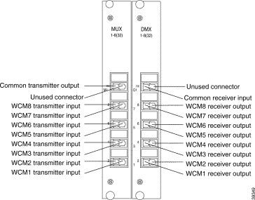
Each MUX and DMX has up to 10 optical connectors:
All connectors are MiniSC. Figure 6-2 show the front panels of the MUX and DMX.
Connecting the MUX and DMX is described in the "Adding and Replacing a MUX and a DMX" section and in "Installation."

To add or replace a MUX and DMX to your unit, follow these instructions:
 |
Warning Only trained and qualified personnel should be allowed to install, replace, or service this equipment. |
 |
Warning Avoid electrostatic discharge. Wear electrostatic wrist strap before operating the system |
Step 2 Skip this step if you are adding a MUX or DMX. Disconnect all jumpers and protect the connectors with dust covers (jumpers) and blind plugs.
Step 3 Remove two screws from the protective front panels of the MUX and DMX.
Step 4 Take the new MUX and DMX modules from their shipping container and use canned, dry, oil-free, compressed air to blow off any possible dust particles.
Step 5 Carefully insert the MUX and DMX modules into the chassis slot while guiding the upper and lower edges of the modules into the proper tracks until the connectors of the modules come into contact with the backplane connectors. You need a force of up to 1 lb (4.5 newton) to push the modules completely into the chassis.
 |
Caution It is critical to insert modules gently. If you need a force greater than 1 lb (4.5 newton) is needed, stop immediately. |
Inspect the first inserted module, if it is not damaged repeat the insertion procedure with the second module.
Step 6 Skip this step if you are replacing a MUX or DMX. Remove the blind plug from the WCM connector labeled R/T and the dust cover from one end of a short jumper. Connect the MiniSC plug to the open WCM connector (Figure 6-3).

Step 7 Remove the dust cover from the other end of the jumper and the blind plug from the corresponding MUX connector. For example, if you interconnect the first WCM of the primary chassis, remove the blind plug from the MUX connector labeled 1 and connect the MiniSC plug to the open MUX connector (Figure 6-3).
Step 8 Skip this step if you are replacing a MUX or DMX. Remove the blind plug from the WCM connector labeled R/R and the dust cover from one end of a short jumper. Connect the MiniSC plug to the open connector (Figure 6-3).
Step 9 Remove the dust cover from the other end of the jumper and the blind plug from the corresponding DMX connector. For example, if you interconnect the first WCM of the primary chassis, remove the blind plug from the DMX connector labeled 1 and connect the MiniSC plug to the open DMX connector (Figure 6-3).
 |
Note Repeat steps 5 to 9 with all other WCMs before proceeding. |
Step 10 Remove the blind plug from the M* labeled connector of the MUX (that is, M1 connector of MUX 1 to 8 of 32) and the dust cover from one end of a jumper. Connect the MiniSC plug to the open connector.
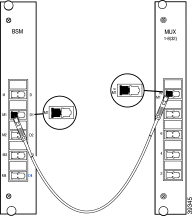
Step 11 Remove the dust cover from the other end of the jumper and the blind plug from the M* labeled connector of the BSM (that is, the M1 connector if you route the MUX 1 to 8 of 32). Connect the plug to the open connector of the BSM as shown in Figure 6-4.

Step 12 Remove the blind plug from the D* labeled connector of the DMX (that is, D1 connector of DMX 1 to 8 of 32) and the dust cover from one end of a jumper. Connect the MiniSC plug to the open connector.
Step 13 Remove the dust cover from the other end of the jumper and the blind plug from the D* labeled connector of the BSM (that is, the D1 connector if you route the DMX 1 to 8 of 32). Connect the plug to the open connector of the BSM as shown in Figure 6-5.

Step 14 Place the fiber-optic cables in the cable holder of the chassis and in the cable holder of the rack at the side of the chassis.
Step 15 Mount the acrylic cover in front of the chassis.
 |
Note If you have any problems that result in a deviation from the installation described here, please contact your Customer Service Representative immediately. |
![]()
![]()
![]()
![]()
![]()
![]()
![]()
![]()
Posted: Tue Jan 23 11:18:11 PST 2001
All contents are Copyright © 1992--2001 Cisco Systems, Inc. All rights reserved.
Important Notices and Privacy Statement.