|
|

This chapter describes the typical tasks to be completed when first using the Cisco 6500/7600 Series Manager, and consists of the following sections:
Table 3-1 outlines the general steps involved in using the C65/76M software.
| Step | Description | |
|---|---|---|
| Step 1 | Refer to the Cisco Element Management Framework Installation and Administration Guide for more information on how to install and start CEMF. |
|
| Step 2 | Refer to the Cisco 6500/7600 Manager Installation Guide for more information. |
|
| Step 3 | Set up the Catalyst 6000 family switch or the Cisco 7600 series Internet Router. |
You must configure the Catalyst 6000 family switch or Cisco 7600 series Internet Router before it can be properly managed by CEMF. Refer to the "Hardware Configuration Requirements" section in the Cisco 6500/7600 Manager Installation Guide for more information. |
| Step 4 | Starting a CEMF user session provides access to all C65/76M functionality. |
|
| Step 5 | Refer to the "Deploying C65/76M Objects" section of this chapter for more information. |
|
| Step 6 | Refer to the "Commissioning C65/76M Objects" section in this chapter for more information. |
The CEMF Launchpad application is the main starting point for using CEMF. The Launchpad can be accessed by starting a CEMF user session.
 |
Note Before you can start a CEMF user session, CEMF has to be running. If a message is displayed indicating that CEMF is not running, contact the system administrator. |
To start a CEMF user session, do the following:
|
Note Replace CEMF_ROOT with the root directory in which CEMF is installed (for example, /opt/cemf). |
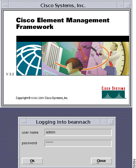
The login window (Figure 3-1) appears.
Step 2 Enter your user name and password, then click Ok to proceed.
|
Note When an invalid user name or password is entered, an error is displayed. Click Ok and then enter a valid user name and password. Three attempts to enter a valid user name and password are allowed. If a valid user name and password are not entered within three attempts, the login window closes. |
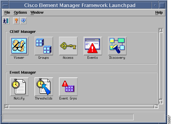
When a valid user name and the password are entered, the session starts and the CEMF Launchpad window appears (see Figure 3-2).
The icons displayed in the Launchpad window (see Figure 3-2) represent applications that are provided by Cisco Element Management Framework (CEMF). The icons and applications are:
For more information, refer to the Cisco Element Management Framework User Guide.
The Viewer icon provides access to the CEMF Map Viewer application, which provides complete flexibility in viewing, building, and monitoring a network using graphical representations of Network Elements. The Map Viewer application is the primary access point for C65/76M management functions.
The Groups icon provides access to the CEMF Object Group Manager application, which provides the opportunity to organize Network Elements into object groups. The Object Group Manager allows the creation, deletion, and modification of object groups. Object groups can be any combination of objects derived from the CEMF managed object class. Objects can be added manually or on the basis of query criteria.
The Access icon provides access to the CEMF User Access Control application, which is a component of Carrier Class Security and provides system administrators the opportunity to control which features of their system can be accessed by various levels of personnel. This is important for security and efficient and effective network management.
The Events icon provides access to the Event Browser application. In CEMF, when a condition (fault) occurs on a managed object in the network, the system is notified immediately. This notification is shown as an event and can be viewed with the Event Browser. One of the most important aspects of network service management is the ability to identify events on the system and to take action to resolve them quickly and efficiently. For example, there may be a power supply fault in a chassis which would require an engineer to be sent out to rectify the fault. This fault is critical to the running of the network and would need prompt attention.
The Discovery icon provides access to the CEMF Auto Discovery application, which examines the network for IP and SNMP devices and creates a managed object for each new device discovered. Auto Discovery can be opened from the CEMF Launchpad window or from a pop-up menu available on a selected object.
The Notify icon provides access to the Notification feature. An important aspect of a monitoring system which captures and reacts to events on the network is when and how a network operator is informed of these events. The CEMF Event Manager uses notifications for providing this information. For example, when the temperature of a module rises 10 degrees above normal, an e-mail might be sent to the network operator warning of a potential problem and a minor event might be generated if the temperature does not fall to within 10 degrees of normal within twenty minutes.
Notification profiles are collections of notifications. Each notification profile has a name and description and can be accessed by all Event Manager users. Each profile includes a list of notifications, and is run following a trigger, which might be an event entering an event group, or a threshold breach in a thresholding regime. For example, when the first event is received by an event group, a notification profile may be triggered that causes a sound to occur, which alerts the operator. As well as audible alerts, a notification can be set up to display on screen, or to trigger an external notification, such as an e-mail.
The Thresholds icon provides access to the Thresholding Regime feature. A Thresholding Regime is a set of threshold conditions for specified object attributes which, when breached, causes one or more notification profiles to be run. The Thresholding Regime defines which attributes should be polled and on what period, and defines the thresholding conditions. The Thresholding Regime specifies object groups that contain the objects whose attributes will be polled.
The Event Grps icon provides access to the Event Groups application, which is used to organize Network Elements into event groups and to view the status of these groups as scoreboards. You can create, delete, and modify event groups and scoreboards. Event groups are available to all users.
Event groups can be any combination of objects derived from the CEMF-managed object class. These groups are set up using queries, which can be configured to match given requirements. For example, a network administrator could choose to monitor a particular device, specify a time period, and choose to look at events that are warnings or critical. You define a query so that the event group only includes the events that meet the specified criteria.
To quit a CEMF user session, follow these steps:
Step 2 A window appears, asking, Do you wish to quit the CEMF Manager System? Click Yes to quit the session. All active applications are closed and the session terminates.
To manage a Catalyst 6000 family switch or Cisco 7600 series Internet Router using CEMF, a C65/76M object must be deployed within CEMF and commissioned. This section describes how to manually deploy the Network Element object in CEMF. For a detailed description on other deployment options, refer to "Deploying the C65/76M."
To manually deploy a Catalyst 6500 Network Element object, follow these steps:
Step 2 Choose Deployment/Deploy Catalyst 6500 Manager from the pop-up menu. This pop-up menu item is available from the Catalyst6500Manager object.
|
Note To deploy other device managers, use the pop-up menu from the other manager containment views. |
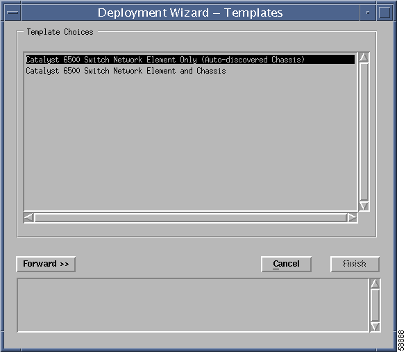
Step 3 When selected, it will display the deployment wizard template screen, shown in Figure 3-3.
Choose the Catalyst 6500 Switch Network Element Only option and click the Forward button.
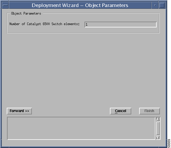
Step 4 Enter the number of switches that are to be deployed at the same time and click the Forward button (see Figure 3-4).
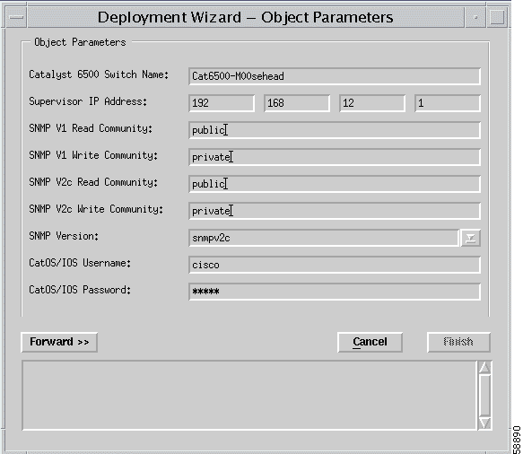
Step 5 Enter the details for the switch and click the Forward button (see Figure 3-5).
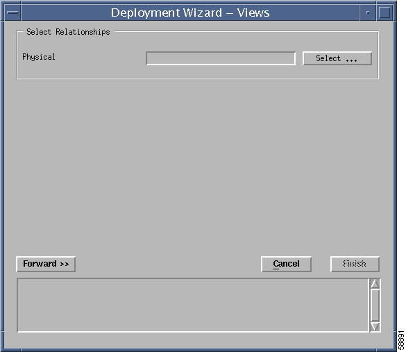
Step 6 Enter the location in the physical containment tree where the switch will appear and click the Forward button (see Figure 3-6).
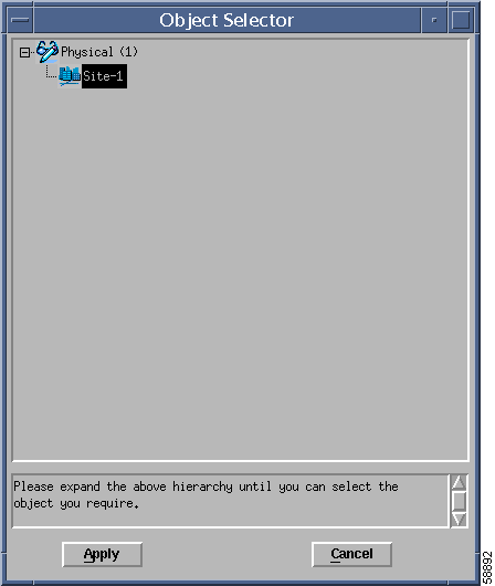
Clicking the Select... button displays the window shown in Figure 3-7, which allows users to select the Physical location parameter.
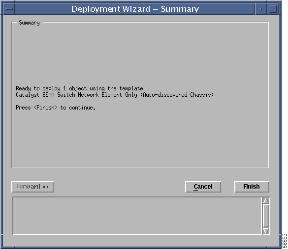
Click the Apply button when the physical containment view has been selected. Click Forward in the Deployment Wizard - Views window. A summary window is displayed (see Figure 3-8).
Step 7 Click the Finish button to deploy the Network Element object.
This procedure deploys a decommissioned Catalyst 6500 Network Element object in CEMF. The next step is to commission the object.
After the Network Element object has been created by the deployment wizard, it must be commissioned to allow CEMF to monitor the switch. When the Network Element object is commissioned, it executes a subchassis discovery process that communicates with the switch to automatically determine the contents of the switch.
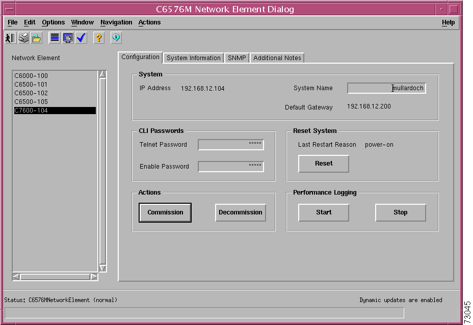
To commission the Network Element object, right-click on the Network Element object and choose Open Network Element Dialog from the pop-up menu, which launches a window that looks similar to Figure 3-9.
From the Configuration tab, choose the Commission button to start the subchassis discovery, which allows the C65/76M to determine the modules that are installed on the device and also allows the CEMF to start monitoring the devices.
|
Note Commissioning may take a few minutes. |
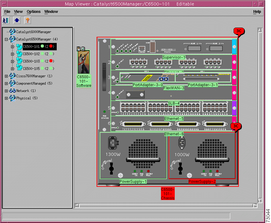
After the object is commissioned, the physical view will resemble Figure 3-10.
|
Note If you have installed hardware that is not supported by C65/76M, the module image will contain a "?" in the hardware view. |
After all the objects in the network element are in the normal state, dialog boxes can be opened to perform management operations on the network element.
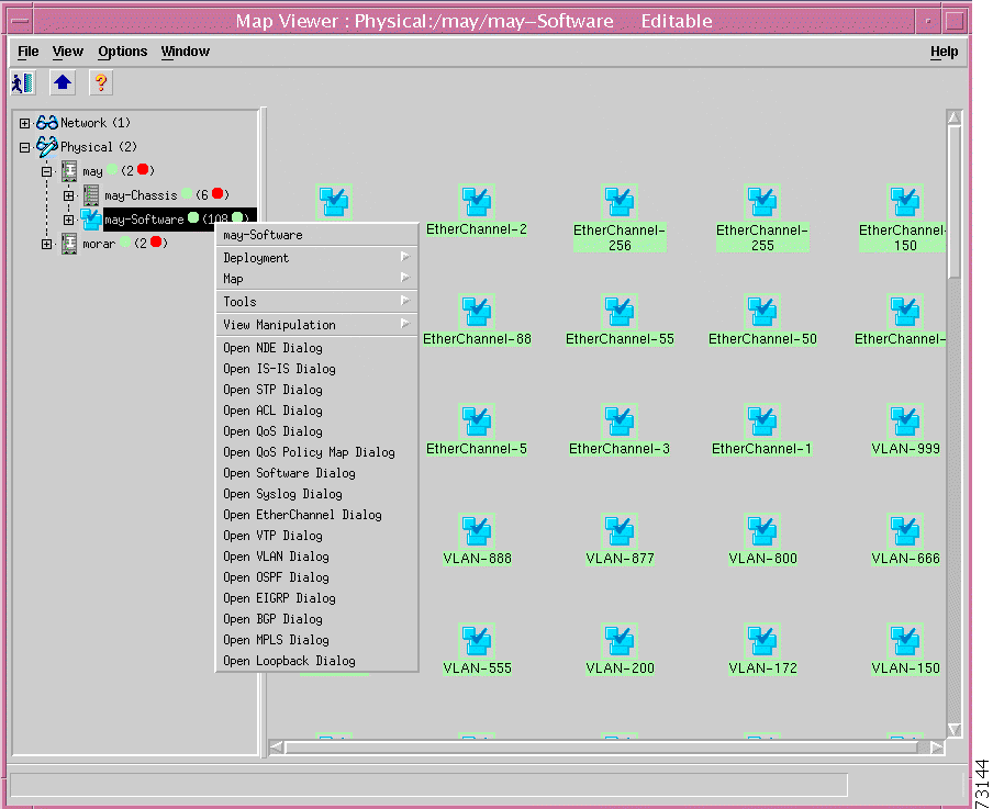
To launch the management dialog box of a C65/76M object, right click its parent object in the Map Viewer application or the object itself in the containment view. Select the option to open the object's dialog box from the pop-up menu. Refer to the "C65/76M Objects and Interfaces" section for descriptions of the object heirarchies.
For example, to open the EtherChannel Dialog, right-click on the Software object and choose Open EtherChannel Dialog from the pop-up menu, as shown in Figure 3-11 .
"Physical Object Dialog Boxes," and "Logical Object Dialog Boxes," describe how to use the dialog boxes for the physical and logical objects, respectively.
![]()
![]()
![]()
![]()
![]()
![]()
![]()
![]()
Posted: Sat Jan 18 09:10:00 PST 2003
All contents are Copyright © 1992--2002 Cisco Systems, Inc. All rights reserved.
Important Notices and Privacy Statement.