|
|

This chapter describes basic concepts and terminology used in this guide, and consists of these sections:
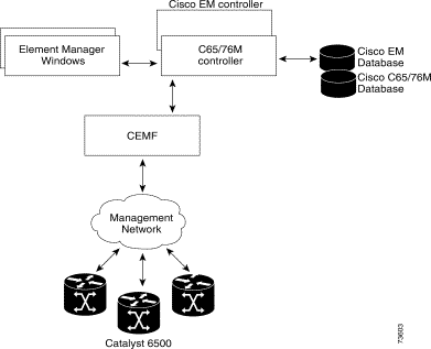
The C65/76M is the carrier-class element manager for the Catalyst 6000 family switches and Cisco 7600 series Internet Routers, which "plugs into" CEMF. The C65/76M software adds additional windows and a back-end controller process that communicates with the hardware elements (using CEMF), as shown in Figure 2-1.

An Element Manager is an application that is responsible for providing fault, configuration, accounting, performance and security (FCAPS) management for a particular type of Network Element or family of Network Elements. The C65/76M software primarily provides fault and performance information. The configuration capabilities are limited, and the accounting information is used for inventory purposes. No security information is provided by the C65/76M.
The C65/76M software provides three types of objects:
The C65/76M software models the following physical components:
These C65/76M objects have the following hierarchical organization:
The C65/76M models the following logical components:
These components have the following hierarchical organization:
The Network Element object is a logical container representing the entire Catalyst 6000 family multilayer switch or Cisco 7600 series Internet Router managed through a single SNMP agent and IOS command-line interface. This class acts as a container for the physical and logical components of the device. The entire hierarchical structure of the C65/76M components is as follows:
Network Element
Chassis
Power Supplies
Supervisor Modules
    Ethernet Interfaces
Ethernet Modules
    Ethernet Interfaces
Switch Fabric Modules
FlexWAN Modules
    Port Adapter
    ATM Port Adapter
        ATM SONET Interfaces
        ATM E3 Interfaces
        ATM T3 Interfaces
OSM GeWAN Modules
    OSM GeWAN Interfaces
OSM POS Modules
    Ethernet Interfaces
    OSM POS Interfaces
OSM Channelized SONET Modules
    Ethernet Interfaces
    OSM Channelized SONET Interfaces
        OSM Serial Sub-interfaces
        OSM POS Sub-interfaces
Content Switching Modules
Software
EtherChannels
Syslog
EIGRP
BGP
OSPF
VTP
VLAN
STP
IS-IS
ACL
NDE
Loopback
QoS
    QoS Policy Map
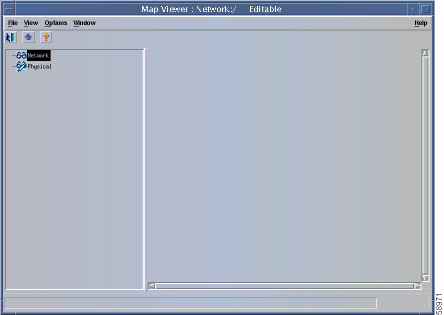
The CEMF Map Viewer application uses a concept called containment views to allow logical grouping of monitored objects. Objects being managed by CEMF must be added to one or more containment views. Objects are organized into different views and can exist in multiple views simultaneously by reference. Objects can be in one or more containment views. Figure 2-2 shows the default network containment view and default physical containment view in the Map Viewer application.

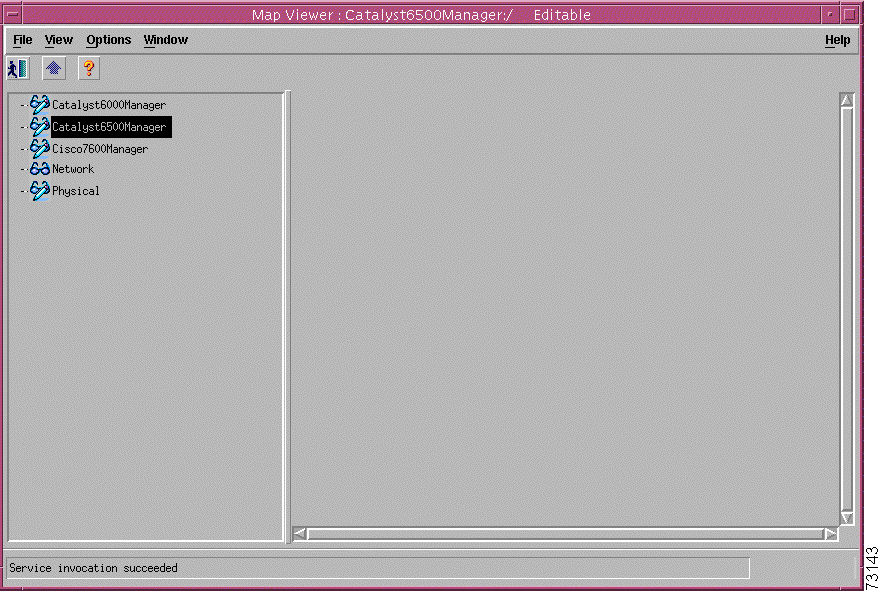
When installed, the C65/76M adds three more containment views into the Map Viewer application:
These containment views are called manager views. Figure 2-3 shows the three C65/76M manager views added to the Map Viewer application.

The Catalyst6000Manager, Catalyst6500Manager, and Cisco7600Manager manager views are used to group together the managed objects of their respective devices. All C65/76M management features and objects are available from these manager views.
 |
Note The C65/76M software and its child objects are only available in the manager views. |
The network view is a standard feature in CEMF. This view is used by the CEMF Auto Discovery feature to determine which devices have already been added to the system so that Auto Discovery does not try to discover the same device multiple times. This view displays all IP devices under their parent network (that is, it groups monitored objects in a network layout). This view provides a logical view of the network structure. For example, devices on the same subnet would be grouped together. Refer to the Cisco Element Management Framework User Guide for more information.
 |
Note The network view does not provide access to the C65/76M software tree. Only the Network Element and the Physical objects are available in the network view. |
The physical view is a standard feature in CEMF. Objects in the physical view are ordered according to their relative geographical or physical location. The relationships defined in this view are physical containment relationships. For example, monitored objects physically located in the same room or location may be grouped together under the same site. Refer to the Cisco Element Management Framework User Guide for more information.
 |
Note The physical view does not provide access to the C65/76M software tree. Only the Network Element and the Physical objects are available in the physical view. |
All C65/76M objects have states associated with them. Each state corresponds to a specific task that is performed in that state. For example, in the performance state, attributes are being polled at a predefined rate. State changes can be triggered by actions, or selected SNMP traps from the device. The state of an object can change frequently, depending upon what actions are being performed on the object. All objects in CEMF have a state assigned to them, which appears at the bottom left corner of each dialog box for a selected object. The following are the two most common object states:
Some states are inherited by an object's children. For example, if a chassis is decommissioned, all subchassis objects are also decommissioned. If performance logging is enabled on a module, performance logging is enabled on all ports of that module.
The decommissioned state indicates that an object is not being managed. When an object is initially deployed, it is normally placed into a decommissioned state. The following actions occur on a decommissioned object:
Decommission buttons can be found within certain windows, dependent upon the type of object selected. When an object is decommissioned, the children of that object also change their state to decommissioned. For example, if a module is decommissioned, all interfaces and connections on that module are decommissioned.
Objects can be put into the decommissioned state from any other state.
The discovery state is a temporary state that is assigned to certain objects during subchassis discovery.
This state applies to the Network Element, Chassis and Software objects. It is used to determine the physical and logical components on a switch. If successful, an automatic state transition to normal is made. If communication is lost, the object transitions to the discovery lostcomms state. If physical components are detected that do not match the expected types, the objects are transitioned to the mismatched state.
The normal state is applicable to all objects, and represents a situation in which an object is regarded as being actively monitored. When an object enters the normal state, CEMF performs heartbeat polling on the object every five minutes to check for connectivity or changes to the object.
This state applies only to the Network Element object. If communication to the Network Element object is lost, it moves into the lostcomms state. Heartbeat polling polls an object every five minutes to verify its existence and current state. Heartbeat polling continues, until the object responds positively to a heartbeat request. When the object can be contacted again, it responds positively to heartbeat requests, and then moves back into the normal state.
This state applies all objects except the Network Element object. This state indicates that communication has been lost to an object that was formerly in the normal state. Two transistions can be made out of this state:
This state applies all physical objects that support Performance Logging. When you enable performance logging on an object in the normal state, the object is moved into the performance state. Specific performance data is collected on the object and can be viewed in the Performance Manager. You can enable performance logging on a global scale or on an individual interface basis. Enabling global performance logging puts all subchassis objects into the performance state.
Performance logging occurs at the specified interval. When you initially enable performance logging or global performance logging on an object, it takes a period of time up to the length of the interval for the data to be collected and become visible in C65/76M performance menus.
Heartbeat polling is performed on an object in the performance state. If the object moves into the lostcomms state, it is returned to the performance state when the error is corrected. For example, if a module is in the performance state and it fails, it moves into the lostcomms state. When heartbeat polling finds the module is back up, it restores the module to the performance state.
There are three transitions out of the performance state:
This state applies all physical objects that support Performance Logging. This state indicates that communication has been lost to an object that was formerly in the performance state. Two transistions can be made out of this state:
If communication to an object is lost, it moves into the lostcomms state. In this state, performance polling (if activated) is stopped; however, heartbeat polling continues, until the object responds positively to a heartbeat request. Heartbeat polling polls an object every five minutes to verify its existence and current state. When the object can be contacted again, it responds positively to heartbeat requests, and then moves back into the previously held state.
The discovery lostcomms state applies to Network Element, Software and Chassis objects. This state is similar to the lostcomms state, except that it only occurs during the discovery process. When connectivity is established with the corresponding object in the device, the discovery is resumed and the object moves out of the discovery lostcomms state.
The mismatched state occurs when a mismatch is found between the type of hardware discovered and what is predeployed in CEMF. For example, if a 48-port 10/100TX, RJ-45 module is expected, the module is predeployed in CEMF to prepare for that type of module. However, when the module becomes available and is placed into the chassis, it is not a 48-port 10/100TX, RJ-45 module, but an 8-port Gigabit Ethernet module. After the C65/76M detects the new module, it finds a mismatch. The module gets placed into the mismatched state and an alarm is raised against the module.
To correct a mismatch problem, the source of the problem must be assessed. If the operator was at fault and predeployed an incorrect module, the operator should delete the predeployed module and deploy the correct module. If the engineer is at fault and inserted the wrong type of module into the chassis, then the module should be removed and replaced.
The mismatched state applies to the following objects:
For the Network Element object, the mismatched state represents the fact that the IP address of the object does not correspond to a Catalyst 6000 family switch or a Cisco 7600 series Internet Router.
![]()
![]()
![]()
![]()
![]()
![]()
![]()
![]()
Posted: Mon Apr 22 12:28:57 PDT 2002
All contents are Copyright © 1992--2002 Cisco Systems, Inc. All rights reserved.
Important Notices and Privacy Statement.