|
|

 |
Warning Before you install, operate, or service the system, read the Site Preparation and Safety Guide. This guide contains important safety information you should know before working with the system. |
Before installing the switch, have all cables and any additional interface equipment on hand. If you intend to build your own cables, see the cable pinouts in "Cabling Specifications and Compliance Information."
For module-specific network connections, refer to the Catalyst 5000 Family Module Installation Guide.
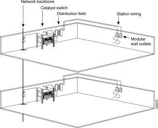
Figure 2-1 shows the following network cabling components:

The length of your networks and the distances between connections depend on the type of signal, the signal speed, and the transmission media (the type of cabling used to transmit the signals). The distance and rate limits in this chapter are the IEEE-recommended maximum speeds and distances for signaling. Review the distance limits in the following sections before you install your network.
As with all signaling systems, serial signals can travel a limited distance at any given bit rate; generally, the slower the baud rate, the greater the distance.
Table 2-1 shows the standard relationship between baud rate and distance for EIA/TIA-232 signals.
| Rate (bps) | Distance (feet) | Distance (meters) |
|---|---|---|
2400 | 200 | 60 |
4800 | 100 | 30 |
9600 | 50 | 15 |
19,200 | 25 | 7.6 |
38,400 | 12 | 3.7 |
56,000 | 8.6 | 2.6 |
Table 2-2 shows the maximum cable distances.
| Transceiver Speed | Cable Type | Duplex Mode | Maximum Distance between Stations |
|---|---|---|---|
10 Mbps | Category 3 UTP1 | Full and half | 328 feet (100 m) |
10 Mbps | Multimode fiber | Full and half | 1.2 miles (2 km) |
100 Mbps | Category 5 UTP | Full and half | 328 feet (100 m) |
100 Mbps | Multimode fiber | Full | 1.2 miles (2 km) |
100 Mbps | Multimode fiber | Half | 1312 feet (400 m) |
1000 Mbps SX | Multimode fiber | Full | 62.5-micron diameter MMF2—722 feet (220 m) 62.5-micron diameter MMF (200/500 MHz-km)—902 feet (275 m) 50-micron diameter MMF (400/400 MHz-km or |
1000 Mbps LX | Multimode fiber | Full | 62.5-micron diameter MMF—1804 feet (550 m) 62.5-micron diameter MMF (200/500 MHz-km)—1804 feet (550 m) |
1000 Mbps LX (continued) |
|
| 50-micron diameter MMF (400/400 MHz-km or |
1000 Mbps LX | Single-mode fiber | Full | 9/10-micron diameter MMF—6.2 miles (10 km) |
| 1UTP=unshielded twisted-pair 2MMF=multimode fiber |
When connecting the 1000BASE-LX/LH uplink port with 62.5-micron diameter multimode fiber (MMF), you must install a mode-conditioning patch cord (Cisco product number CAB-GELX-625 or equivalent) between the uplink port and the MMF cable on both the transmit and receive ends of the link. The patch cord is required for link distances greater than 984 feet (300 m); otherwise, an effect called differential mode delay (DMD) might degrade link performance. For more information about DMD, refer to "Differential Mode Delay."
 |
Note For very short link distances (tens of meters), we do not recommend using a 1000BASE-LX/LH uplink port with MMF and no patch cord. The result could be an elevated bit error rate (BER). |
 |
Note The patch cord is required to comply with IEEE standards. The IEEE found that link distances could not be met with certain types of fiber-optic cable due to a problem in the center of some fiber-optic cable cores. The solution is to launch light from the laser at a precise offset from the center, which is accomplished by using the patch cord. At the output of the patch cord, the switch uplink port is compliant with the IEEE 802.3z standard for 1000BASE-LX. For a detailed description of this problem, see the "Fiber-Optic Cabling Distances" section. |
 |
Note Cisco Gigabit Ethernet products have been tested and evaluated to comply with the standards listed in "Cabling Specifications and Compliance Information." Equivalent cables should also meet these standards. |
Figure 2-2 shows a typical configuration using the patch cord.

Plug the end of the patch cord labeled "To Equipment" into the interface (see Figure 2-3). Plug the end labeled "To Cable Plant" into the patch panel.

The maximum distances for fiber-optic network connections are determined by the transmitter output power, receiver sensitivity, and type of optical source. Table 2-3 shows the distance specifications.
| Item | Description |
|---|---|
Transmitter output power | -19 to -14 dBm1 |
Receiver sensitivity | -32.5 to -14 dBm |
Wavelength | 1270 to 1380 nm2 |
Optical source | LED |
Maximum span | 1.2 miles (2 km) |
| 1decibels per milliwatt 2nanometer |
The power budget (PB) is the maximum possible amount of power transmitted. The following equations show the calculation of the power budget:
PB = PT - PR
PB = -18.5 dBm - 30 dBm
PB = 11.5 dB
The following is an example of multimode power budget calculations with sufficient power for transmission, based on the following variables:
Using these variables, estimate the power budget as follows:
PB = 11.5 dB - 3 km (1.0 dB/km) - 4 (0.5 dB) - 3 (0.5 dB) - 0.5 dB (HOL) - 1 dB (CRM)
PB = 11.5 dB - 3 dB - 2 dB - 1.5 dB - 0.5 dB - 1 dB
PB = 3.5 dB
The 3.5-dB value indicates that this link would have sufficient power for transmission.
The following example has the same parameters as the previous example, but with a multimode link distance of 4 kilometers (2.5 miles):
PB = 11.5 dB - 4 km (1.0 dB/km) - 4 (0.5 dB) - 3 (0.5 dB) - 0.5 dB (HOL) - 1 dB (CRM)
PB = 11.5 dB - 4 dB - 2 dB- 1.5 dB - 0.5 dB - 1 dB
PB = 2.5 dB
The 2.5-dB value indicates that this link would have sufficient power for transmission. However, because of the dispersion limit on the link (4 km x 155.52 MHz > 500 MHz/km), this link would not operate with multimode fiber. In this case, single-mode fiber is the better choice.
Statistical models can more accurately determine the power budget than the worst-case method. Determining the link loss with statistical methods requires accurate knowledge of variations in the data-link components. Statistical power budget analysis is beyond the scope of this publication. For further information, refer to User-Network Interface (UNI) Forum specifications, ITU-T standards, and your equipment specifications.
 |
Note The International Telecommunication Union Telecommunication Standardization Sector (ITU-T) carries out the functions of the former Consultative Committee for International Telegraph and Telephone (CCITT). |
The LED used for a multimode transmission light source creates multiple propagation paths of light, each with a different path length and time requirement to cross the optical fiber, causing signal dispersion (smear). Higher order loss results from light from the LED entering the fiber and being radiated into the fiber cladding. A worst-case estimate of power margin (PM) for multimode transmissions assumes minimum transmitter power (TP), maximum link loss (LL), and minimum receiver sensitivity (PR). The worst-case analysis provides a margin of error, although not all the parts of an actual system will operate at the worst-case levels.
The power margin calculation is derived from the power budget and subtracts the link loss, as follows:
PM = PB - LL
If the power margin is positive, the link will work. Table 2-4 shows the maximum cable transmission distances.
| Transceiver Type | Maximum Distance (100 Mbps) | Maximum Distance (1000 Mbps) |
|---|---|---|
Single-mode | 6.2 miles (10 km) | 6.2 miles (10 km) |
Multimode | 1.2 miles (2 km) | 853 feet (260 m) |
Category 5 UTP | 328 ft (100 m) | - |
Table 2-5 lists the factors that contribute to link loss and the estimate of the link-loss value attributable to those factors. After calculating the power budget minus the data link loss, the result should be greater than zero. Results less than zero can indicate insufficient power to operate the receiver.
| Link Loss Factor | Estimate of Link Loss Value |
|---|---|
Higher-order mode losses | 0.5 dB |
Clock recovery module | 1 dB |
Modal and chromatic dispersion | Dependent on fiber and wavelength used |
Connector | 0.5 dB |
Splice | 0.5 dB |
Fiber attenuation | 1 dB/km |
When planning your connections, consider the types and locations of connectors on adjacent switching modules to avoid overlapping the transceiver and impairing access to other connections.
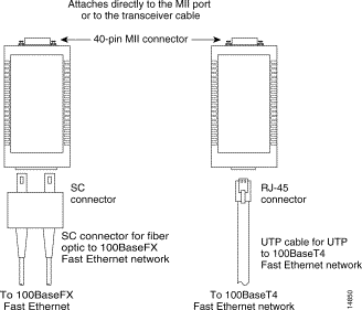
Ethernet transceivers are available from a variety of sources for unshielded twisted-pair (UTP) and multimode fiber-optic cabling (100BASE-FX at 100 Mbps). Figure 2-4 shows an example of Fast Ethernet transceivers and connection equipment.
You might need additional data communications equipment to complete your installation.

![]()
![]()
![]()
![]()
![]()
![]()
![]()
![]()
Posted: Tue Oct 3 18:54:01 PDT 2000
Copyright 1989-2000©Cisco Systems Inc.