|
|

Console interfacing can be established by connecting to the CONSOLE serial port on the back panel of the Catalyst 3000. Use this connection to set up:
NMS application (in-band management) is discussed in Chapter 9, "Monitoring Port Activity with Application Software." For more detailed information, see the guide that accompanies the NMS software.
This chapter explains how to connect and create a console session for configuration, monitoring, and downloading the Catalyst 3000.
The following topics are discussed in this chapter:
The following steps explain connecting a console to the Catalyst 3000:
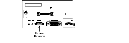
Step 1 Connect the Catalyst 3000 to a PC or other DTE (Data Terminal Equipment) device using a straight, 25-pin to 9-pin EIA (RS)-232 cable and a null modem adapter. See Appendix A for a description of the cables and adapters.
Step 2 Connect the EIA-232 cable to the DB-9 connector (CONSOLE) on the back panel of the Catalyst 3000. The male DB-9 connector on the Catalyst 3000 is configured as a DTE device.
See Figure 6-1 for a view of the cable connection to the back panel of the Catalyst 3000. The console cable connector is marked CONSOLE.
Step 3 Use the following table, Table 6-1, to set the console configuration parameters.
| Baud rate | 2400, 4800, 9600, 19.2K, 38.4K, 57.6K (default: 9600) |
| Parity | None |
| Data bits | 8 |
| Stop bits | 1 |
| Handshaking | None |
| Terminal emulation | VT100 |
| Duplex | Full |
| Soft flow control (XON/XOFF) | Off (input and output) |
| Hard flow control (RTS/CTS) | Off |
| Autobaud upon break | On |
| Line wrap | On |
| Screen scroll | On |
| CR translation | CR |
| Backspace (BS) translation | Destructive |
| Break length (milliseconds) | 350 |
| Enquiry (ENQ) | Off |
| EGA/VGA true underline | Off |
| Terminal width | 890 |
| ANSI 7 or 8 bit commands | 7 |
| Microsoft Windows, terminal emulation | Disable the "Use Function, Arrow, and Ctrl Keys for Windows" option, located in the Terminal Preference menu |
Step 4 At power on (cold boot), the Catalyst 3000 performs a series of self-test diagnostics that verify that hardware components are functioning. An example of the self-test diagnostic screen is shown later in this chapter.
The three main types of communications problems you may encounter are, no communication, garbled communication, or dropped characters. This section explains how to resolve these problems.
 Caution Hardware handshaking must be turned on at both the terminal and the Catalyst 3000 and you must have a 7-wire or a 9-wire cable to the terminal. If hardware handshaking is off and you are using a 3-wire cable, a catastrophic failure of the Catalyst 3000 could occur.
Caution Hardware handshaking must be turned on at both the terminal and the Catalyst 3000 and you must have a 7-wire or 9-wire cable to the terminal. If hardware handshaking is off and you are using a 3-wire cable, a catastrophic failure of the Catalyst 3000 could occur.
Caution Hardware handshaking must be turned on at both the terminal and the Catalyst 3000 and you must have a 7-wire or a 9-wire cable to the terminal. If hardware handshaking is off and you are using a 3-wire cable, a catastrophic failure of the Catalyst 3000 could occur.
Caution Hardware handshaking must be turned on at both the terminal and the Catalyst 3000 and you must have a 7-wire or 9-wire cable to the terminal. If hardware handshaking is off and you are using a 3-wire cable, a catastrophic failure of the Catalyst 3000 could occur.
The diagnostic self-test displays two different screens (lists of information), depending on whether you perform a cold boot (power on cycle with full diagnostics), or a warm boot (a reset without full diagnostics).
During a cold boot, the following is an example of the list of messages that appear on the console screen in sequence, as the tests are performed. The warm boot contains portions of this list.
Cisco Catalyst Boot Firmware P/N 57-1327-02, Copyright 1995
- Initiating bootstrapping sequence.
- Boot image integrity check...Passed.
- Control transferred to boot process.
- Relocating main image to DRAM.......Done.
- Main image integrity check...succeeded.
- Control transferred to main process.
Cisco Catalyst 3000 System Software Version 1.1.1-B7, Copyright 1994, 1995.
System started on Fri. November 17, 1995  13:02:46
4 Megabytes System memory
2 Megabytes Network memory
- Initialization started
- File system initialized
- System temperature is within safe operating levels
- Warmboot initialization started
- Checking file system integrity
- LAN ports detected:
  - 10Base-T  : 1 2 3 4 5 6 7 8 9 10 11 12 13 14 15 16
  - StkPort   : 25
- Initializing Ports: 1 2 3 4 5 6 7 8 9 10 11 12 13 14 15 16 25
- Initializing system address table
- No existing diagnostic information, forcing diagnostic mode
- Starting Power Up Diagnostics test
  - UART loopback test on diagnostic port...Passed
  - UART loopback test on console port...Passed
  - RTC memory test...Passed
  - Real Time Clock test...Passed
  - CPU loopback test..............Passed
  - Ethernet Port loopback test...................Passed
  - Ethernet Port fast transmit loopback test...................Passed
  - Ethernet Port fast receive loopback test...................Passed
  - Ethernet Port cross port loopback test...................Passed
  - Ethernet Port broadcast test...................Passed
  - Catalyst Stack Port loopback test...Passed
  - Catalyst Stack Port cross port loopback test...Passed
  - Catalyst Stack Port broadcast test...Passed
  - CPU broadcast test...Passed
- Completed Power Up Diagnostics test
- System entering stand-alone mode
- Catalyst  initiating bootp requests on one or more VLANs
- System initialization complete
- Enabling port: 1 2 3 4 5 6 7 8 9 10 11 12 13 14 15 16 25
Press RETURN key to activate console...
Verify that all diagnostics have passed and that the FAULT LED is off. If the FAULT LED is on, read the screen to determine which test has failed. Power cycle the Catalyst 3000 to re-run the diagnostics to see if that will clear the error. If the error does not clear, see Chapter 10, "Troubleshooting," to help find the cause.
To work within the console menus, follow these guidelines:
For more information on the Greeting screen see Chapter 7, "Console Configuration."
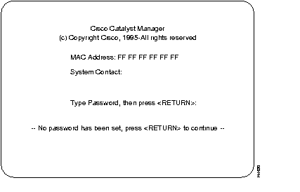
Greeting Screen:
Use the Password menu to add, change, or delete a password. If you establish a password, users must enter it to access the Console menus. If there is no password, just press RETURN at the password prompt.
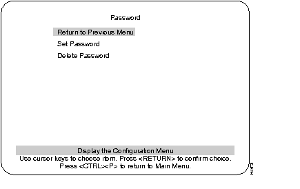
Establishes or changes the password.
Deletes the password.
The system prompts you to enter the present password before it allows you to change or delete the password. If you are establishing a new password, press RETURN at the Set Password prompt.
The password is saved across warm boots and power cycles.
Use the arrow keys (also referred to as cursor keys) to move the highlight over a selection. If the selection is a menu, pressing the RETURN key displays a new screen of information; if the selection is a command, such as Reset, pressing the RETURN key initiates that function.
A heading with three dots after it means that when that heading is selected more information about that heading is displayed.
Unless specified differently, all the screens or menus are accessed in the same way.
The following lists the headings for the Main menu screen and a description of those headings.
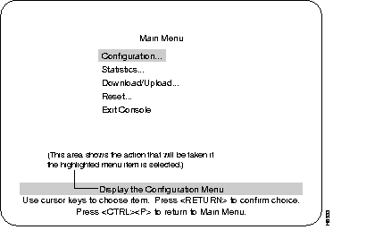
Displays the Configuration menu, which enables you to view and set the Catalyst 3000 configuration parameters. The Configuration section and its sub-menus are described in Chapter 7, "Console Configuration."
Displays Statistics menu for the Catalyst 3000. Explanations of screens in the Statistics Menu are in Chapter 8, "Monitoring the Network With Out-of-Band Management."
Download Menu From the Main Menu is explained later in this chapter.
The Reset Menu is explained in this chapter after the sections describing downloading.
Highlighting this selection and pressing the RETURN key return the console to the Greeting screen (on a Telnet session, this causes the session to close).
Information within the menus and sub-menus are described in subsequent chapters. These chapters include configuring, monitoring, and viewing statistics on the Catalyst 3000 or the Catalyst Stack.
The following sections describe the downloading/uploading features for the Catalyst 3100.
The Download menu is accessed from the Main Menu.
Downloading is used to load the Flash Memory within the Catalyst 3000. The Download menu displays two download choices; Serial Link Download and Trivial File Transfer Protocol (TFTP Download). The following sections describe both types.
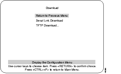
Serial Link download is for downloading via the console. Selecting the Serial Link download displays a prompt requesting to "confirm new code download via serial port (Y or N)." Selecting Yes starts the Serial Link downloading. Follow the prompts as they are displayed.
TFTP is not invoked automatically on the Catalyst 3000 as it is on certain other network devices, such as a diskless workstation. This is because there should normally be a functional software image in Flash memory and, therefore, TFTP is not a standard part of the Catalyst 3000 bootup procedure. TFTP is intended for use during software upgrades and, once a new image is installed, there should be no need for TFTP until the next software upgrade is installed.
In view of this, the TFTP function in the Catalyst 3000 is designed as an explicitly requested operation with operator-settable parameters. Note that changes to these parameters may be altered and are used when starting a download in the display. However they are not recorded until the display is exited normally.
The TFTP Download menu is accessed through the Main Menu. From the Main Menu select the Download Menu and then select the TFTP Download Menu.
The following is the TFTP Download Menu:
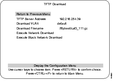
The address of the host serving as the TFTP server.
The VLAN name through which the download is attempted.
The file the Catalyst 3000 attempts to download, as it is to be received and interpreted by the TFTP server. (The security mode in use on the TFTP server may affect this.)
The function Execute Network Download initiates the download. The screen displays which block it last received from the server (Block 0 if no reply has been received), until the last packet arrives. The Catalyst 3000 does not attempt to load any of the image into FLASH memory until it receives the final packet. Therefore, if the download is interrupted or cancelled for any reason before the transmission of the last packet, the previous system image remains intact in FLASH memory.
Caution Do not use this function for downloading to a Stack configurations
I Caution f the process is interrupted during this time, the stored image may be corrupted and the Catalyst 3000 will not be able to boot normally. Once the last packet has arrived, the Catalyst 3000 immediately begins clearing FLASH memory and then loading it with the new image.
The Catalyst 3000 continues to use its previously loaded software until its next reset by whatever means, then the newly stored image becomes functional.
Use this function for a Stack configuration. This function initiates downloading for the Stack. The procedure is similar to the above single stand-alone Catalyst 3000 download; however, the Stack download procedure downloads to the entire Stack of switches in one operation. (Downloading is done one switch at a time, until all of the switches are completed.)
When the Stack download procedure is used, only the same code or the same level of code can be downloaded for all of the switches in the Stack.
This section describes how to establish a console or Telnet session.
The explanation for the selections in the Console Configuration menu follows the view of the Console Configuration screen.
Console Configuration screen: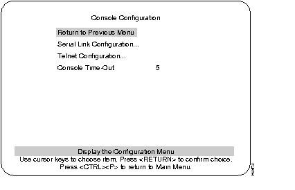
An example of that screen and an explanation of its contents follows.
An example of that screen and an explanation of its contents follows.
A value that can be set to determine when the console session will timeout and return to the Greeting menu. If the value is set to zero, the console will never time out.
Serial Link Configuration Menu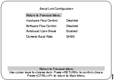
Enables or disables RTS/CTS handshaking.
Default: Disabled
Enables the XON and XOFF characters, which are 11 and 13 hex, respectively.
Default: Disabled
Enables the Autobaud feature. When a BREAK key is sent or received the baud rate is reset when you press the RETURN key rapidly for five seconds. It is recommended that this feature is not disabled.
Default: Enabled
Default: 9600
Use the Serial Link Configuration Menu to configure the Catalyst 3000 in order to communicate with a console via a modem.
Use the following steps to set up a modem:
Step 1 Wait for a Connection should be set to 45 sec.
Step 2 Pause Between Calls should be set to 6 sec.
Step 3 Have Autobaud detect On.
Step 4 Set Drop DTR (Data Terminal Ready) between calls to Yes.
Step 5 Set Send CR between calls to Yes.
Step 6 Set Send init if CD high to Yes
Start the console by pressing RETURN. If a Telnet session is active, press RETURN at the console to terminate the Telnet session and press RETURN again to start the console session.
Pressing Ctrl-P returns the console session to the Main Menu and pressing Ctrl-B returns to the Greeting Menu.
A Telnet session can be terminated abnormally in a UNIX environment, especially by being killed by another process. If the user environment seems to have locked after termination of the Telnet session, try typing <CTRL><J>stty sane<CTRL><J>. Because the Telnet Server is doing the echoing for the user, the user's terminal capabilities are modified for the duration of the Telnet Session due to the Telnet option negotiation. If the user's Telnet process or task is abruptly terminated, the user's terminal may be left in a no-echo, raw mode.
The following menu and functions describe Telnet configurations.
Telnet configuration screen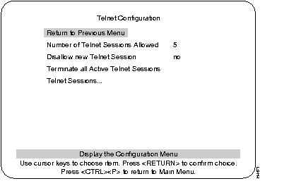
Returns to Console Configuration menu.
Limits the number of Telnet sessions. Numbers allowed are from 1 to 5. Highlight this selection and press RETURN and enter the number.
Choice of Yes or No to allow or disallow a new Telnet session. Press RETURN at this selection and use arrow keys to highlight Yes or No and press RETURN.
If this selection is highlighted and RETURN is pressed any Telnet sessions will be terminated.
Shows status of Remote and Local Telnet sessions.
Telnet Sessions screen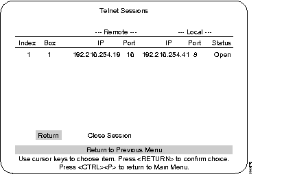
Numerical order of entries.
The number ID of the Catalyst 3000 in a Stack.
Lists the IP address and the port number of the Remote Telnet session.
Lists the IP address and the port number of the Local Telnet session.
The observe the following when starting a Telnet session to the Catalyst 3000.
The Telnet session can be terminated by pressing Ctrl-B or any other means available through the user's Telnet application.
The following can terminate a Telnet session:
TFTP Upload/Download allows you to copy the whole image of NVRAM to a file on a UNIX server and to retrieve the NVRAM image from the server to the switch. The purpose for this is to store a current copy of the NVRAM as a backup or to be able to store the contents of NVRAM in a temporary place while changes are made on the switch. You will need to go to three menus, as describe in the following sections, before you can begin the actual upload and download procedures.
Do not download NVRAM images from different software versions (for instance,
NVRAM from version 1.3 is not compatible with version 2.0) and from different platform configurations (for instance, NVRAM from a Catalyst 3000 is not compatible with NVRAM from a Catalyst 3000).
Before uploading the whole NVRAM image to a UNIX server, make sure the upload file names have been created on the UNIX server and that the following default values are entered correctly in the Config Files TFTP Upload menu:
Use the following single switch or Stack console menu examples (Figure 6-2 and Figure 6-3) to TFTP upload the file.
Main Menu
Return to Previous Menu
Config Filename (all for complete NVRAM image) all
Filename on the server ( your filename prefix) Anyname
Execute Config File Network Upload
Config files TFTP Upload Menu
Return to Previous Menu
Config Filename (all for complete NVRAM image) all
Filename on the server ( your filename prefix) Anyname
Execute Config File Switch Network Upload
Execute Config File Stack Network Upload
In a Stack configuration, there are options to upload the NVRAM image from an individual switch as well as from all the switches in the Stack. The heading Execute Config File Switch Network Upload in the Config Files TFTP Upload menu uploads individual boxes and the heading Execute Config File Stack Network Upload uploads for the entire Stack.
You do not need the filename suffix (.xx box number) to download the software to the switch. This is automatically done from the switch from which you want to download the software.
The switch or Stack should be reset after a successful download of the the NVRAM image.
As with uploading you should enter the following information into the Config Files TFTP Download menu (see Figure 6-4):
Caution Do not download NVRAM images from different software versions (for instance, NVRAM from version 1.3 is not compatible with version 2.0) and from different platform configurations (for instance, NVRAM from a Catalyst 3000 is not compatible with NVRAM from a Catalyst 3000).
Use the following menu (Figure 6-4) to TFTP download the NVRAM file for a single switch.
Config files TFTP Download
Return to Previous Menu
Config Filename all
Filename on the server Image
Execute Config File Network Download
You can either upgrade the NVRAM on one switch of your choice or upgrade the software for the entire Stack.
In a Stack configuration, there are options to download the NVRAM image from an individual switch as well as from all of the switches in a Stack. The heading Execute Config File Switch Network Download in the Config Files TFTP Download menu downloads individual boxes and the heading Execute Config File Stack Network Download downloads the entire Stack.
If you choose Execute Config File Stack Network Download to download a Stack of boxes, the files with the suffix names (.xx) that correspond to the same box number will download the image in that file to that box number. For example, mystack.0 will download its image to box 0, mystack.4 will download to box 4 and mystack.7 would download to box7.
Use the following menu (Figure 6-5) to TFTP download the NVRAM file for a Stack.
Config files TFTP Download
Return to Previous Menu
Config Filename all
Filename on the server Image
Execute Config File Switch Network Download
Execute Config File Stack Network Download
The Reset menu is accessed from the Main Menu.
The Reset screen, as shown below, displays the reset options available with the
Catalyst 3000.
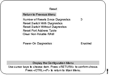
Number of times the switch has been reset since the switch was powered on or ran power-on diagnostics. This is an informational heading. The data cannot be changed.
This number is not reset to 0 when Non-volatile RAM is cleared.
The following four headings within the Reset menu are command functions that can be selected and initiated by moving the highlight over the heading and pressing RETURN.
A reset function is initiated with this selection. It resets the switch hardware; runs diagnostic tests; clears all counters, including address tables; and restarts the Catalyst 3000. When the Catalyst 3000 reboots, administrative parameters from nonvolatile memory are used to initialize the operational parameters. This takes approximately 4 to 5 minutes.
This command resets the switch hardware; clears all counters, including address tables; and starts the Catalyst 3000. When the Catalyst 3000 reboots, administrative parameters from nonvolatile memory are used to initialize the operational parameters. This takes approximately 40 seconds.
Selecting this command clears all address table entries for a specified port (user is queried for which port to reset), sets port traffic counters to zero, and sets Time Since Last Reset for this port to zero.
Deletes all user-configured parameters; baud rate, IP address information, EtherChannel, VLAN, Spanning Tree, and then resets the switch.
If you must clear NVRAM, use the following guidelines:
This is a selectable option that determines whether diagnostics are, or are not, initiated during power-on. To change the selection, highlight the heading and press RETURN, then select Enabled or Disabled, and press RETURN.
Default: Enabled
|
|