|
|

This appendix lists cables that have been tested and verified for use with the Catalyst 3000. It also includes minimum pinout information. If you use a cable that is not listed, you must verify that the cables used in your installation are wired correctly.
This appendix covers the following topics:
10BaseT ports on the Catalyst 3000 are always MDI-X. Cabling these ports to different types of equipment will require a straight-through cable or a crossover cable.
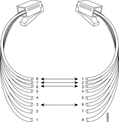
A "straight-through" cable is used when connecting two ports that are not set to the same MDI mode or not set to the same MDI-X mode. 10BaseT ports on the Catalyst 3000 are always MDI-X. When connecting these MDI-X ports to ports that are MDI, such as PCs or servers, use a straight-through cable. A straight-through cable has each internal twisted pair of wires connected to the same pin number at each end. The twisted-pair wires must be twisted throughout the entire length of the cable. The wiring sequence must conform to AT&T 258A (not USOC). Figure A-1 shows the wiring diagram for a straight-through cable, and Table A-1, "10BaseT Cable PinOut," is a listing of the signals used on each pin.

Pins 1 and 2 must be a twisted pair.
Pins 3 and 6 must be a twisted pair.
Pins 4, 5, 7, and 8 are not used in this application, although they may be wired in the cable.
The following table (Table A-1) lists the pin numbers and their respective signal names for a 10BaseT straight-through cable.
| Pin | Signal | Note |
|---|---|---|
| 1 | TX+ |
Pins 4, 5, 7, and 8 are not used. |
| 2 | TX- | |
| 3 | RX+ | |
| 6 | RX- |
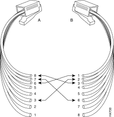
For cabling between two switches, the transmit and receive pairs must be reversed. You can do this in one of two ways:
Figure A-2 shows the wiring diagram for a crossover cable.

Pins 1 and 2 at A, must be a twisted pair wired through to pins 3 and 6, respectively, at B.
Pins 3 and 6 at A, must be a twisted pair wired through to pins 1 and 2, respectively, at B.
Pins 4, 5, 7, and 8 are not used in this application, although they may be wired in the cable.
A short crossover cable can be used to adapt a straight-through twisted-pair cable for "cascading" switches through the twisted-pair ports.
The 100BaseTX expansion module network port is always MDI-X. Cabling to different types of equipment will require a straight-through or a crossover cable.
| Transceiver end 15-pin Female | Switch end 15-pin Male | Signal |
|---|---|---|
| 2 | 2 | Control In circuit A |
| 3 | 3 | Data Out circuit A |
| 4 | 4 | Data In circuit Shield (common drain) |
| 5 | 5 | Data In circuit A |
| 6 | 6 | Voltage common |
| 9 | 9 | Control In circuit B |
| 10 | 10 | Data Out circuit B |
| 12 | 12 | Data In circuit B |
| 13 | 13 | Voltage plus (+12 @ 500ma) |
For this connection, you can use:
Some longer cables may have all 15 pins wired. See the IEEE 802.3 standards document for definitions of the pins not shown here.
| Cable Function | Port Type on Terminal, PC, or Modem | Standard Cable or Cable Solution |
|---|---|---|
Connecting a terminal or PC to the console port with an EIA(RS)-232-C | 25-pin female | Attach a null modem adapter++ (Tandy Null Modem Adapter No. 26-1496 has been tested) to the console port. Then attach a straight-through modem cable to the null modem adapter. |
9-pin male | Use a Black Box PC/AT Serial Printer Cable (EVENBPC has been tested). OR: | |
Connecting a modem to the console port | 25-pin female or male port | Straight-through EIA-232-C modem cable (standard cable) |
* For these cables, the signals DTR (pin 20) and RTS (pin 4) must be on, or high, on your terminal or in your terminal emulation program. | ||
The Catalyst 3000 has a DB-9 console port that automatically detects baud rate. The default is 9600 baud; other supported baud rates are 1200, 2400, 4800, and 19200.
For a terminal connection, use a null-modem cable or a straight cable with a null modem adapter attached.
For a modem connection, use a standard modem (straight) cable.
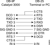
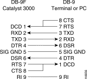
The following table (Table A-4) and two figures (Figure A-3 and Figure A-4) detail pin assignment information for the cables you can use on the console port of the Catalyst 3000.
| Pin | Function |
|---|---|
| 1 | DCD |
| 2 | RXD |
| 3 | TXD |
| 4 | DTR |
| 5 | SIG GND |
| 6 | DSR |
| 7 | RTS |
| 8 | CTS |
| 9 | RI |
The following figures (Figure A-3 and Figure A-4) detail pin assignment information for the cables you can use on the console port of the Catalyst 3000.


|
|