|
|

Table Of Contents
FastEthernet Switch Front Panel Descriptions
Gigabit Ethernet Switch Front Panel Descriptions
Product Overview
The Catalyst 3560 switch—also referred to as the switch—is an Ethernet switch to which you can connect devices like Cisco Wireless Access Point workstations, Cisco IP Phones, and other network devices such as servers, routers, and other switches. This chapter provides a functional overview of the Catalyst 3560 switch. These topics are included:
•
Features
Setting up the Switch
See the Catalyst 3560 Switch Getting Started Guide that shipped with the switch for instructions on how to use Express Setup to initially configure your Catalyst switch. The Getting Started Guide also covers switch management options, basic rack-mounting procedures, port and module connections, power connection procedures, and troubleshooting help.
For instructions on setting up your switch using the command-line interface (CLI), see Appendix C, "Configuring the Switch with the CLI-Based Setup Program."
Features
The Catalyst 3560 switch can be deployed as a backbone switch, aggregating 10BASE-T and 100BASE-TX Ethernet traffic from other network devices. See the switch software configuration guide for examples showing how you might deploy the switch in your network.
These are the switch features:
•
–
–
–
–
•
–
–
–
–
•
–
–
–
–
–
–
Note
•
•
–
–
–
•
•
–
Front Panel Description
The Catalyst 3560 switch front panel descriptions include these sections:
•
•
•
•
FastEthernet Switch Front Panel Descriptions
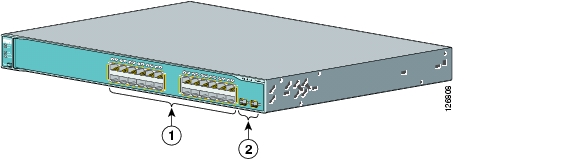
The 10/100 PoE ports on the Catalyst 3560-24PS switch are grouped in pairs. The first member of the pair (port 1) is above the second member (port 2) on the left, as shown in Figure 1-1. Port 3 is above port 4, and so on. The SFP module slots are numbered 1 and 2.
Figure 1-1 Catalyst 3560-24PS Switch Front Panel
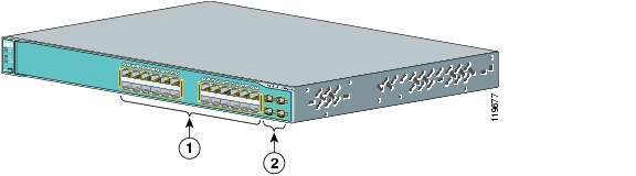
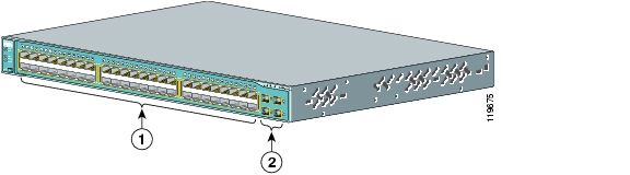
The 10/100 PoE ports on the Catalyst 3560-24TS-S switch are grouped in pairs. The first member of the pair (port 1) is above the second member (port 2) on the left, as shown in Figure 1-2. Port 3 is above port 4, and so on. The SFP module slots are numbered 1 and 2.
Figure 1-2 Catalyst 3560-24TS-S Switch Front Panel
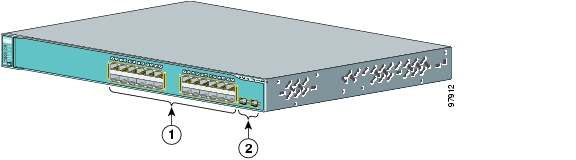
The 10/100 PoE ports on the Catalyst 3560-48PS switch are grouped in pairs. The first member of the pair (port 1) is above the second member (port 2) on the left, as shown in Figure 1-3. Port 3 is above port 4, and so on. The SFP module slots are numbered 1 to 4.
Figure 1-3 Catalyst 3560-48PS Switch Front Panel
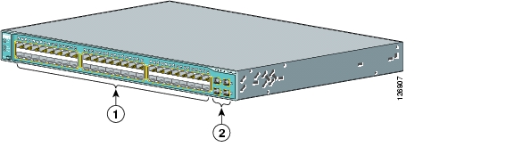
The 10/100 ports on the Catalyst 3560-48TS-S switch are grouped in pairs. The first member of the pair (port 1) is above the second member (port 2) on the left, as shown in Figure 1-8. Port 3 is above port 4, and so on. The SFP module slots are numbered 1 to 4.
Figure 1-4 Catalyst 3560G-48TS-S Switch Front Panel
Gigabit Ethernet Switch Front Panel Descriptions
The 10/100/1000 PoE ports on the Catalyst 3560G-24PS switch are grouped in pairs. The first member of the pair (port 1) is above the second member (port 2) on the left, as shown in Figure 1-5. Port 3 is above port 4, and so on. The SFP module slots are numbered 25 to 28.
Figure 1-5 Catalyst 3560G-24PS Switch Front Panel
The 10/100/1000 ports on the Catalyst 3560-24TS switch are grouped in pairs. The first member of the pair (port 1) is above the second member (port 2) on the left, as shown in Figure 1-6. Port 3 is above port 4, and so on. The SFP module slots are numbered 25 to 28.
Figure 1-6 Catalyst 3560G-24TS Switch Front Panel
The 10/100/1000 PoE ports on the Catalyst 3560G-48PS switch are grouped in pairs. The first member of the pair (port 1) is above the second member (port 2) on the left, as shown in Figure 1-7. Port 3 is above port 4, and so on. The SFP module slots are numbered 49 to 52.
Figure 1-7 Catalyst 3560G-48PS Switch Front Panel
The 10/100/1000 ports on the Catalyst 3560G-48TS switch are grouped in pairs. The first member of the pair (port 1) is above the second member (port 2) on the left, as shown in Figure 1-8. Port 3 is above port 4, and so on. The SFP module slots are numbered 49 to 52.
Figure 1-8 Catalyst 3560G-48TS Switch Front Panel
10/100 and 10/100/1000 Ports
You can set the 10/100 ports on the Catalyst 3560 switches to operate in any combination of half duplex, full duplex, 10 Mbps, or 100 Mbps. You can set the 10/100/1000 ports to operate in 10 or 100 Mbps in half or full duplex or in 1000 Mbps in full duplex.
You can set both the 10/100 and the 10/100/1000 ports for speed and duplex autonegotiation, in compliance with IEEE 802.3ab. (The default setting is autonegotiate.)
Note
When set for autonegotiation, the port senses the speed and duplex settings of the attached device and advertises its own capabilities. If the connected device also supports autonegotiation, the switch port negotiates the best connection (the fastest line speed that both devices support and full-duplex transmission if the attached device supports it) and configures itself accordingly. In all cases, the attached device must be within 328 feet (100 meters).
Warning
The10/100 ports on the Catalyst 3560-24PS and 3560-48PS switches and the 10/100/1000 ports on the Catalyst 3560G-24PS and 3560G-48PS switches provide PoE support for devices compliant with IEEE 802.3af and also provide Cisco pre-standard PoE support for Cisco IP Phones and Cisco Aironet Access Points.
Each of the Catalyst 3560-24PS switch 10/100 ports or the Catalyst 3560G-24PS switch 10/100/1000 ports can deliver up to 15.4 W of PoE. On the Catalyst 3560-48PS or 3560G-48PS switches, any 24 of the 48 10/100 or 10/100/1000 ports can deliver 15.4 W of PoE, or any combination of the ports can deliver an average of 7.7 W of PoE at the same time, up to a maximum switch power output of 370 W.
On a per-port basis, you can control whether or not a Catalyst 3560 PoE port automatically provides power when an IP phone or an access point is connected. The Cluster Management Suite (CMS), Network Assistant, and the CLI provide two PoE settings for each 10/100 or 10/100/1000 PoE port: Auto and Never.
When you select the Auto setting, the port provides power only if a valid powered device, such as an IEEE 802.3af-compliant powered device, a Cisco pre-standard IP phone, or a Cisco pre-standard Cisco access point, is connected to it. The Auto setting is the default. However, when you select the Never setting, the port does not provide power even if a Cisco IP phone or an access point is connected to it.
Cisco enhanced power negotiation allows some powered devices, such as the Cisco 7970G IP Phone, to operate in high-power mode on Catalyst 3560 PoE switches. The powered device and the switch negotiate through power-negotiation Cisco Discovery Protocol (CDP) messages for an agreed-upon power-consumption level. The negotiation allows a high-power Cisco powered device that consumes more than 7 W to operate at its highest power mode. The powered device first boots up in low-power mode, consumes less than 7 W, and negotiates to obtain enough power to operate in high-power mode. The device changes to high-power mode only when it receives confirmation from the switch. High-power devices can operate in low-power mode on switches that do not support power-negotiation CDP.
For information about configuring and monitoring PoE ports, see the switch software configuration guide.
Note
If the primary source fails, the second power source becomes the primary power source to the powered device. During the power transfer, an IP phone might reboot or reestablish link with the switch.For information about Cisco IP Phones and Cisco Aironet Access Points, see the documentation that came with your IP phone or access point.
Note
When connecting the switch to workstations, servers, routers, and Cisco IP Phones, be sure that the cable is a straight-through cable. When connecting the switch to switches or hubs, use a crossover cable. When using a straight-through or crossover cable for 1000BASE-T connections, be sure to use a twisted four-pair, Category 5 cable for proper operation. Pinouts for the cables are described in Appendix B, "Connector and Cable Specifications."
Note
The Auto-MDIX feature is enabled by default on switches running Cisco IOS Release 12.2(18)SE or later. For releases between Cisco IOS Release 12.1(14)EA1 and 12.2(18)SE, the Auto-MDIX feature is disabled by default. For configuration information for this feature, see the switch software configuration guide or the switch command reference.
Note
SFP Module Slots
The SFP module slots support the SFP modules that are listed in the Catalyst 3560 release notes.
SFP Modules
The Catalyst 3560 switch uses Gigabit Ethernet SFP modules to establish fiber-optic and 1000BASE-T connections. These transceiver modules are field-replaceable, providing the uplink interfaces when inserted in an SFP module slot. You can use the SFP modules for Gigabit uplink connections to other switches. You use fiber-optic cables with LC or MT-RJ connectors to connect to a fiber-optic SFP module. You use Category 5 cable with RJ-45 connectors to connect to a copper SFP module.
The Catalyst 3560 models support these Cisco SFP modules:
•
•
•
•
•
•
For more information about these SFP modules, see your SFP module documentation.
SFP Module Patch Cable
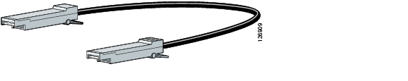
The Catalyst 3560 switch supports the SFP module patch cable, a 1/2 meter, copper, passive cable with SFP module connectors at each end (see Figure 1-9). The patch cable can connect two Catalyst 3560 switches in a cascaded configuration.
Figure 1-9 SFP Module Patch Cable
See "Inserting and Removing the SFP Module Patch Cable" section on page 2-18 for more information about using the SFP module patch cable.
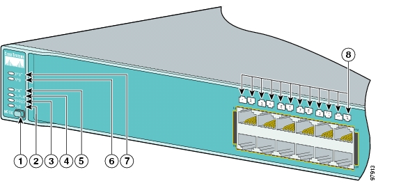
LEDs
You can use the switch LEDs to monitor switch activity and its performance. Figure 1-10 shows the switch LEDs and the Mode button that you use to select one of the port modes.
All of the LEDs described in this section are visible in the CMS and Network Assistant GUIs. The switch online help describes how to use CMS or Network Assistant to configure and monitor individual switches and switch clusters.
Figure 1-10 Catalyst 3560 Switch LEDs
Note
System LED
The System LED shows whether the system is receiving power and is functioning properly. Table 1-1 lists the LED colors and their meanings.
Table 1-1 System LED
Off
System is not powered on.
Green
System is operating normally.
Amber
System is receiving power but is not functioning properly.
For information on the System LED colors during the power-on self-test (POST), see the "Verifying Switch Operation" section on page 2-6.
RPS LED
The RPS LED shows the RPS status. Table 1-2 lists the LED colors and their meanings.
For more information about the Cisco RPS 675, see the Cisco RPS 675 Redundant Power System Hardware Installation Guide.
Port LEDs and Modes
Each RJ-45 port and SFP module slot has a port LED. These port LEDs, as a group or individually, display information about the switch and about the individual ports. The port modes determine the type of information displayed through the port LEDs. Table 1-3 lists the mode LEDs and their associated port mode and meaning.
To select or change a mode, press the Mode button until the desired mode is highlighted. When you change port modes, the meanings of the port LED colors also change. Table 1-5 explains how to interpret the port LED colors in different port modes.
Table 1-3 Modes for Port LEDs
STAT
Port status
The port status. This is the default mode.
DUPLX
Port duplex mode
The port duplex mode: full duplex or half duplex.
SPEED
Port speed
The port operating speed: 10, 100, or 10001 Mbps.
PoE
PoE port power
The PoE status.
1 When installed in Catalyst 3560 switches, 1000BASE-T SFP modules can operate at 10, 100, or 1000 Mbps in full-duplex mode or at 10 or 100 Mbps in half-duplex mode.
Even if PoE mode is not selected, the PoE LED still shows PoE problems when they are detected.
Table 1-4 lists the PoE mode LED colors and their meanings. The PoE LED applies only to Catalyst 3560 switches that support PoE.
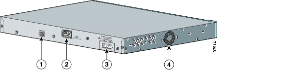
Rear Panel Description
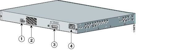
The Catalyst 3560 switch rear panel has an AC power connector, an RPS connector, and an RJ-45 console port. (See Figure 1-11 and Figure 1-12 for examples of the Catalyst 3560 rear panels.)
Figure 1-11 Catalyst 3560-24PS and 3560-48PS Switch Rear Panel
Figure 1-12 Catalyst 3560G-24PS, 3560G-48PS, 3560G-24TS, and 3560G-48TS Switch Rear Panel
Power Connectors
The switch is powered through the internal power supply. You can also connect the Cisco RPS 675 to provide backup power if the switch internal power supply should fail.
Note
Internal Power Supply Connector
The internal power supply is an autoranging unit that supports input voltages between 100 and 240 VAC. Use the supplied AC power cord to connect the AC power connector to an AC power outlet.
Cisco RPS Connector
The switch is powered through the internal power supply. You can also connect the Cisco RPS 675 redundant power supply (model PWR675-AC-RPS-N1=) to provide backup power if the switch internal power supply should fail.
Note
Cisco RPS 675
The Cisco RPS 675 as two output levels: -48 V and 12 V, with a total maximum output power of 675 W. Use the supplied RPS connector cable to connect the RPS to the switch.
Warning
The RPS is a redundant power system that can support six external network devices and provides power to one failed device at a time. It automatically senses when the internal power supply of a connected device fails and provides power to the failed device, preventing loss of network traffic. For more information on the Cisco RPS 675, see the Cisco RPS 675 Redundant Power System Hardware Installation Guide.
Console Port
You can connect the switch to a PC by means of the console port and the supplied RJ-45-to-DB-9 female cable. If you want to connect the switch console port to a terminal, you need to provide an RJ-45-to-DB-25 female DTE adapter. You can order a kit (part number ACS-DSBUASYN=) containing that adapter from Cisco. For console port and adapter pinout information, see the "Connector and Cable Specifications" section on page B-1.
Management Options
The Catalyst 3560 switches offer several management options:
•
CMS is a GUI that can be launched from anywhere in your network through a web browser. CMS is already bundled in the switch. The CMS plug-in is required to run CMS through your web browser. The plug-in is supported both in Windows environments and on Solaris platforms.
You can download the latest CMS plug-in from these URLs:
–
–
From CMS, you can fully configure and monitor a switch or switch clusters, display network topologies to gather link information, and display switch images to modify switch- and port-level settings. For more information, see the "Getting Started with CMS" chapter of the switch software configuration guide on Cisco.com and the online help for this application.
•
Cisco Network Assistant is a free software program that you download from Cisco.com and run on your PC. It offers advanced options for configuring and monitoring multiple devices, including switches, switch clusters, switch stacks, routers, and access points. Network Assistant is free—there is no charge to download, install, or use it.
Follow these steps:
a.
You must be a registered Cisco.com user, but you need no other access privileges.
b.
c.
d.
See the Network Assistant online help and the getting started guide for more information.
•
The switch CLI is based on Cisco IOS software and is enhanced to support desktop-switching features. You can fully configure and monitor the switch and switch cluster members from the CLI. You can access the CLI either by connecting your management station directly to the switch console port or by using Telnet from a remote management station. See the Catalyst 3560 Switch Command Reference on Cisco.com for more information.
For setup instructions that use the CLI, go to Appendix C, "Configuring the Switch with the CLI-Based Setup Program."
•
The CiscoView device-management application displays the switch image that you can use to set configuration parameters and to view switch status and performance information. The CiscoView application, which you purchase separately, can be a standalone application or part of a Simple Network Management Protocol (SNMP) platform. See the CiscoView documentation for more information.
•
You can manage switches from a SNMP-compatible management station that is running platforms such as HP OpenView or SunNet Manager. The switch supports a comprehensive set of Management Information Base (MIB) extensions and four Remote Monitoring (RMON) groups. See the switch software configuration guide on Cisco.com and the documentation that came with your SNMP application for more information.
Network Configurations
See the switch software configuration guide on Cisco.com for an explanation of network configuration concepts. The software configuration guide also provides examples of network configurations that use the switch to create dedicated network segments that are interconnected through Ethernet connections.
![]()
![]()
![]()
![]()
![]()
![]()
![]()
![]()
Posted: Thu Apr 14 13:39:38 PDT 2005
All contents are Copyright © 1992--2005 Cisco Systems, Inc. All rights reserved.
Important Notices and Privacy Statement.