|
|

Table Of Contents
Connector and Cable Specifications
Cable and Adapter Specifications
Two Twisted-Pair Cable Pinouts
Four Twisted-Pair Cable Pinouts for 1000BASE-T Ports
Crossover Cable and Adapter Pinouts
Connector and Cable Specifications
This appendix describes the Catalyst 3560 switch ports and the cables and adapters that you use to connect the switch to other devices.
Connector Specifications
These sections describe the connectors used with the Catalyst 3560 switch.
10/100 and 10/100/1000 Ports
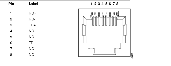
The 10/100 and 10/100/1000 Ethernet ports use standard RJ-45 connectors and Ethernet pinouts with internal crossovers. These ports have the transmit (TD) and receive (RD) signals internally crossed so that a twisted-pair straight-through cable and adapter can be attached to the port. Figure B-1 shows the pinout for a 10/100 port.
Figure B-1 10/100 Port Pinouts
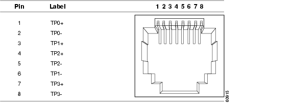
Figure B-2 shows the pinout for a 10/100/1000 port.
Figure B-2 10/100/1000 Port Pinouts
CautionPoE faults are caused when noncompliant cabling or powered devices are connected to a PoE port. Only standard-compliant cabling can be used to connect Cisco pre-standard IP Phones or wireless access points or IEEE 802.3af-compliant devices to PoE ports. A cable or device that causes a PoE fault must be removed from the network.
When connecting 10/100 and 10/100/1000 ports to compatible devices such as servers, workstations, and routers, you can use a two or four twisted-pair straight-through cable wired for 10BASE-T and 100BASE-TX. Figure B-5 shows the two twisted-pair straight-through cable schematics. Figure B-7 shows the four twisted-pair straight-through cable schematics.
When connecting the ports to other devices, such as switches or repeaters, you can use a two or four twisted-pair crossover cable. Figure B-6 shows the two twisted-pair crossover cable schematics. Figure B-8 shows the four twisted-pair crossover cable schematics.
Note
The Auto-MDIX feature is enabled by default on switches running Cisco IOS Release 12.2(18)SE or later. For releases between Cisco IOS Release 12.1(14)EA1 and 12.2(18)SE, the Auto-MDIX feature is disabled by default. For configuration information for this feature, see the switch software configuration guide or the switch command reference.You can use Category 3, 4, or 5 cabling when connecting to 10BASE-T-compatible devices. You must use Category 5 cabling when connecting to 100BASE-TX-compatible devices.
Note
This applies only to switches on which Auto-MDIX is disabled.SFP Module Ports
The Catalyst 3560 switch uses SFP modules for fiber-optic and copper uplinks. See the Catalyst 3560 release notes for a list of supported SFP modules.
Figure B-3 Fiber-Optic SFP Module LC Connector
Warning
Figure B-4 Copper SFP Module RJ-45 Connector
Console Port
The console port uses an 8-pin RJ-45 connector, which is described in Table B-1 and Table B-2. The supplied RJ-45-to-DB-9 adapter cable is used to connect the console port of the switch to a console PC. You need to provide a RJ-45-to-DB-25 female DTE adapter if you want to connect the switch console port to a terminal. You can order a kit (part number ACS-DSBUASYN=) containing that adapter from Cisco. For console port and adapter pinout information, see Table B-1 and Table B-2.
Cable and Adapter Specifications
These sections describe the cables and adapters used with Catalyst 3560 switches.
Two Twisted-Pair Cable Pinouts
Figure B-5 and Figure B-6 show the schematics of two twisted-pair cables for connecting to 10BASE-T- and 100BASE-TX-compatible devices.
Figure B-5 Two Twisted-Pair Straight-Through Cable Schematic
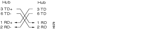
Figure B-6 Two Twisted-Pair Crossover Cable Schematic
Four Twisted-Pair Cable Pinouts for 1000BASE-T Ports
Figure B-7 and Figure B-8 show the schematics of four twisted-pair cables for 1000BASE-T SFP module ports on Catalyst 3560 switches.
Figure B-7 Four Twisted-Pair Straight-Through Cable Schematic for 1000BASE-T Ports
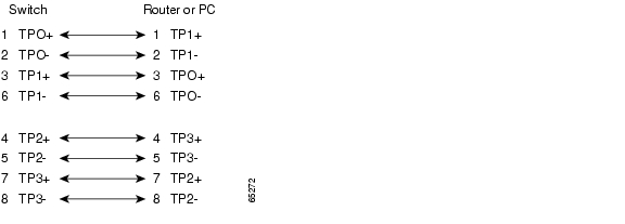
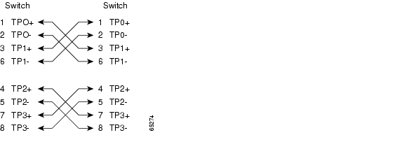
Figure B-8 Four Twisted-Pair Crossover Cable Schematics for 1000BASE-T Ports
Crossover Cable and Adapter Pinouts
This section describes how to identify a crossover cable and also describes the adapter pinouts.
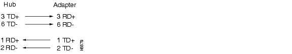
Identifying a Crossover Cable
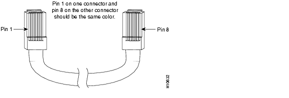
To identify a crossover cable, compare the two modular ends of the cable. Hold the cable ends side-by-side, with the tab at the back. The wire connected to the pin on the outside of the left plug should be the same color as the wire connected to the pin on the outside of the right plug. (See Figure B-9.)
Figure B-9 Identifying a Crossover Cable
Adapter Pinouts
Table B-1 lists the pinouts for the console port, the RJ-45-to-DB-9 adapter cable, and the console device.
Table B-2 lists the pinouts for the console port, RJ-45-to-DB-25 female DTE adapter, and the console device.
Note
![]()
![]()
![]()
![]()
![]()
![]()
![]()
![]()
Posted: Thu Apr 14 13:40:49 PDT 2005
All contents are Copyright © 1992--2005 Cisco Systems, Inc. All rights reserved.
Important Notices and Privacy Statement.