|
|

Table Of Contents
Installing and Removing SFP Modules
Installing SFP Modules into SFP Module Slots
Removing SFP Modules from SFP Module Slots
Inserting and Removing the SFP Module Patch Cable
Connecting to the 10/100 or 10/100/1000 Ports
Connecting to Fiber-Optic SFP Modules
Connecting to 1000BASE-T SFP Modules
Switch Installation
This chapter describes how to start your switch and how to interpret the power-on self-test (POST) that ensures proper operation. It also describes how to install the switch and how to make connections to the switch. Read the topics and perform the procedures in this order:
•
Installing and Removing SFP Modules
•
•
Preparing for Installation
This section covers these topics:
•
Warnings
These warnings are translated into several languages in the Regulatory Compliance and Safety Information for the Catalyst 3560 Switch document that shipped with the switch.
Warning
Warning
Warning
Warning
Warning
Warning
Warning
Warning
Warning
Warning
Warning
Warning
Warning
Warning
Warning
.
Warning
Warning
Warning
Warning
Warning
Installation Guidelines
When determining where to place the switch, be sure to observe these requirements:
•
•
Table 2-1 Fiber-Optic SFP Module Port Cabling Specifications
1000BASE-SX
850
MMF
62.5
62.5
50
50160
200
400
500722 feet (220 m)
902 feet (275 m)
1640 feet (500 m)
1804 feet (550 m)1000BASE-LX/LH
1300
MMF1
SMF62.5
50
50
9/10500
400
500
—1804 feet (550 m)
1804 feet (550 m)
1804 feet (550 m)
32,810 feet (10 km)1000BASE-ZX
1550
SMF
9/10
—
43.4 to 62 miles (70 to 100 km)2
100BASE-FX
Min.: 1270
Typical: 1300
Max.: 1380MMF
50/125
62.5/125500
6,562 feet (2 km)
CWDM
1470, 1490, 1510, 1530, 1550, 1570, 1590, 1610
SMF
9/125
—
62 miles (100 km)
1 A mode-conditioning patch cord is required. Using an ordinary patch cord with MMF, 1000BASE-LX/LH SFP modules, and a short link distance can cause transceiver saturation, resulting in an elevated bit error rate (BER). When using the LX/LH SFP module with 62.5-micron diameter MMF, you must also install a mode-conditioning patch cord between the SFP module and the MMF cable on both the sending and receiving ends of the link. The mode-conditioning patch cord is required for link distances greater than 984 feet (300 m).
2 1000BASE-ZX SFP modules can send data up to 62 miles (100 km) by using dispersion-shifted SMF or low-attenuation SMF; the distance depends on the fiber quality, the number of splices, and the connectors.
Note
When the fiber-optic cable span is less than15.43 miles (25 km), you should insert a 5-decibel (dB) or 10-dB inline optical attenuator between the fiber-optic cable plant and the receiving port on the 1000BASE-ZX SFP module at each end of the link.•
•
–
–
–
•
•
•
Note
Verifying Package Contents
Note
The switch is shipped with these items:
•
•
•
•
•
•
–
–
–
–
–
–
–
–
Verifying Switch Operation
Before installing the switch in a rack, on a wall, or on a table or shelf, you should power the switch and verify that the switch passes POST. See Section 3, "Running Express Setup," in the getting started guide for the steps required to connect a PC to the switch and to run Express Setup.
If your configuration has an RPS, connect the switch and the RPS to the same AC power source. See the "Power Connectors" section on page 1-14, and see the Cisco RPS documentation for more information.
Note
To power on the switch, connect one end of the AC power cord to the AC power connector on the switch, and connect the other end of the power cord to an AC power outlet.
Warning
When the switch powers on, it automatically begins the POST, a series of tests that verifies that the switch functions properly. When the switch begins POST, the system LED slowly blinks green. When POST completes, the system LED blinks amber. If POST fails, the system LED remains amber. If POST completes successfully, the system LED rapidly blinks green.
Note
Powering Off the Switch
After a successful POST, disconnect the power cord from the switch. Install the switch in a rack, on a wall, on a table, or on a shelf as described in the "Installing the Switch" section.
Installing the Switch
This section describes these installation procedures:
Rack-Mounting
To install the switch in a 19-inch or 24-inch rack (24-inch racks require optional mounting hardware), follow the instructions described in these procedures:
•
•
•
Note
Removing Screws from the Switch
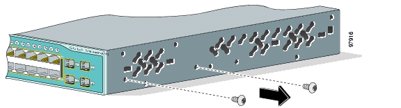
If you plan to install the switch in a rack, you must first remove screws in the switch chassis so that mounting brackets can be attached. Figure 2-1 shows how to remove the chassis screws in a Catalyst 3560 switch.
Figure 2-1 Removing Screws from the Catalyst 3560 Switch
Attaching Brackets to the Catalyst 3560 Switch
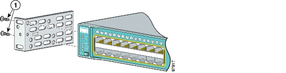
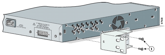
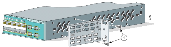
The bracket orientation and the brackets that you use depend on whether you are attaching the brackets for a 19-inch or a 24-inch rack. For 19-inch racks, use bracket part number 700-8209-01; for 24-inch racks, use bracket part number 700-13248-01. Figure 2-2 through Figure 2-7 show how to attach each type bracket to one side of the switch. Follow the same steps to attach the second bracket to the opposite side.
Figure 2-2 Attaching Brackets for 19-Inch Racks to a Catalyst 3560 Switch, Front Panel Forward
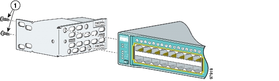
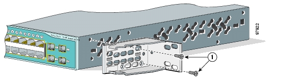
Figure 2-3 Attaching Brackets for 24-Inch Racks to a Catalyst 3560 Switch, Front Panel Forward
Figure 2-4 Attaching Brackets for 19-Inch Racks to a Catalyst 3560 Switch, Rear Panel Forward
Figure 2-5 Attaching Brackets for 24-Inch Racks to a Catalyst 3560 Switch, Rear Panel Forward
Figure 2-6 Attaching Brackets for 19-Inch Telco Racks to a Catalyst 3560 Switch
Figure 2-7 Attaching Brackets for 24-Inch Telco Racks to a Catalyst 3560 Switch
Mounting the Switch in a Rack
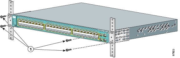
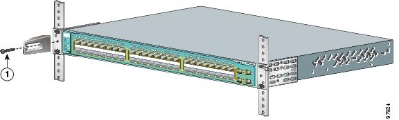
After the brackets are attached to the switch, use the four supplied number-12 Phillips machine screws to securely attach the brackets to the rack, as shown in Figure 2-8.
Figure 2-8 Mounting the Catalyst 3560 Switch in a Rack
After the switch is mounted in the rack, you need to do these tasks to complete the installation:
•
•
•
For configuration instructions about using the CLI setup program, go to Appendix C, "Configuring the Switch with the CLI-Based Setup Program."
Attaching the Cable Guide
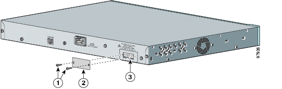
We recommend attaching the cable guide to prevent the cables from obscuring the front panel of the switch and the other devices installed in the rack. Use the supplied black screw shown in Figure 2-9 to attach the cable guide to the left or right bracket.
Figure 2-9 Attaching the Cable Guide on the Catalyst 3560 Switch
Wall-Mounting
To install the switch on a wall, follow the instructions in these procedures:
•
•
•
Attaching the Brackets to the Switch for Wall Mounting
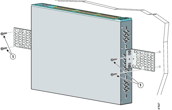
Figure 2-10 shows how to attach a 19-inch bracket to one side of the switch. Follow the same steps to attach the second bracket to the opposite side.
Figure 2-10 Attaching the 19-inch Brackets for Wall Mounting
Attaching the RPS Connector Cover
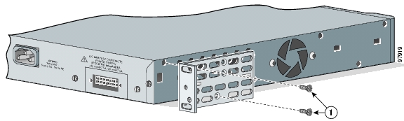
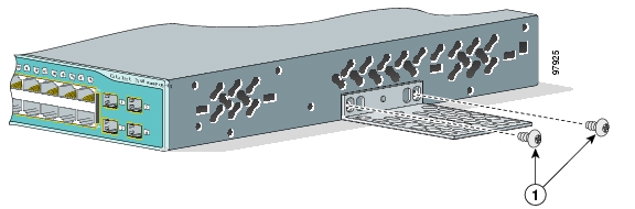
If you are not using an RPS with your switch, use the two Phillips pan-head screws to attach the RPS connector cover to the back of the switch, as shown in Figure 2-11.
Warning
Figure 2-11 Attaching the RPS Connector Cover on the Catalyst 3560 Switch
Mounting the Switch on a Wall
For the best support of the switch and cables, make sure the switch is attached securely to wall studs or to a firmly attached plywood mounting backboard. Mount the switch with the front panel facing up, as shown in Figure 2-12.
Warning
Figure 2-12 Mounting the Switch on a Wall
After the switch is mounted in the rack, you need to do these tasks to complete the installation:
•
•
•
For configuration instructions about using the CLI setup program, go to Appendix C, "Configuring the Switch with the CLI-Based Setup Program."
Table- or Shelf- Mounting
Follow these steps to install the switch on a table or shelf:
Step 1
Note
Step 2
After the switch is mounted in the rack, you need to do these tasks to complete the installation:
•
•
•
For configuration instructions about using the CLI setup program, go to Appendix C, "Configuring the Switch with the CLI-Based Setup Program."
Note
Installing and Removing SFP Modules
These sections describe how to install and remove SFP modules. The modules are inserted into the SFP module slots on the front of the Catalyst 3560 switches. These field-replaceable modules provide uplink interfaces.
You can use any combination of SFP modules. See the Catalyst 3560 release notes for the list of SFP modules that the Catalyst 3560 switches support. Each port must match the wave-length specifications on the other end of the cable, and for reliable communications, the cable must not exceed the stipulated cable length. See the "Installation Guidelines" section for cable stipulations for SFP connections.
Use only Cisco SFP modules on the Catalyst 3560 switch. Each SFP module has an internal serial EEPROM that is encoded with security information. This encoding provides a way for Cisco to identify and validate that the SFP module meets the requirements for the switch.
For detailed instructions on installing, removing, and cabling the SFP module, see the SFP module documentation.
Installing SFP Modules into SFP Module Slots
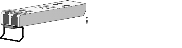
Figure 2-13 shows an SFP module that has a bale-clasp latch.
Caution
Removing and installing an SFP module can shorten its useful life. Do not remove and insert SFP modules more often than is absolutely necessary.
Figure 2-13 SFP Module with a Bale-Clasp Latch
To insert an SFP module into the module slot, follow these steps:
Step 1
Step 2
Note
Step 3
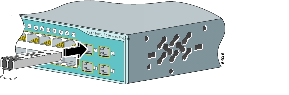
Step 4
Figure 2-14 Installing an SFP Module into an SFP Module Slot
Step 5
Caution
Step 6
•
•
Note
Removing SFP Modules from SFP Module Slots
To remove an SFP module from a module receptacle, follow these steps:
Step 1
Step 2
Tip
Step 3
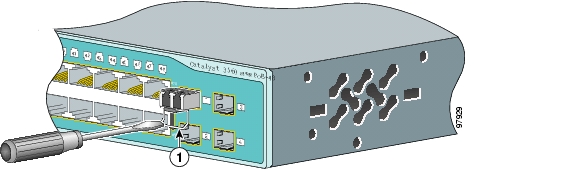
If the module has a bale-clasp latch, pull the bale out and down to eject the module. If the bale-clasp latch is obstructed and you cannot use your index finger to open it, use a small, flat-blade screwdriver or other long, narrow instrument to open the bale-clasp latch.
Figure 2-15 Removing a Bale-Clasp Latch SFP Module by Using a Flat-Blade Screwdriver
Step 4
Step 5
Step 6
Inserting and Removing the SFP Module Patch Cable
To insert an SFP module patch cable into the SFP module slot, follow these steps:
Step 1
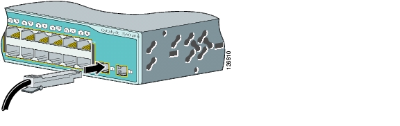
Step 2
Figure 2-16 Inserting an SFP Module Patch Cable into an SFP Module Slot
Step 3
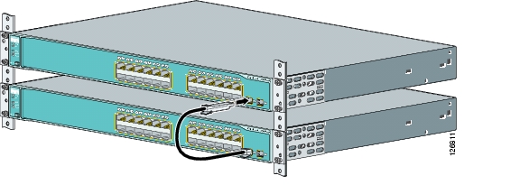
Figure 2-17 Connecting Two Catalyst 3560 Switches with an SFP Module Patch Cable
To remove an SFP module patch cable from the SFP module slot, release the connector, and pull it from the SFP module slot.
Connecting to the 10/100 or 10/100/1000 Ports
The switch 10/100 and 10/100/1000 ports configure themselves to operate at the speed of attached devices. If the attached ports do not support autonegotiation, you can explicitly set the speed and duplex parameters. Connecting devices that do not autonegotiate or that have their speed and duplex parameters manually set can reduce performance or result in no linkage.
Note
Warning
To maximize performance, choose one of these methods for configuring the Ethernet ports:
•
•
You can configure the 10/100 or 10/100/1000 ports on the Catalyst 3560 PoE switches either to automatically provide PoE when a Cisco IP Phone, Cisco Aironet Access Point, or end device compliant with IEEE 802.3af is connected or to never to provide PoE, even if an IP phone or an access point is connected. The default setting is Auto. To prevent electrostatic-discharge (ESD) damage, follow your normal board and component handling procedures.
Follow these steps to connect to 10BASE-T or 100BASE-TX devices:
Step 1
Caution
Note
The Auto-MDIX feature is enabled by default on switches running Cisco IOS Release 12.2(18)SE or later. For releases between Cisco IOS Release 12.1(14)EA1 and 12.2(18)SE, the Auto-MDIX feature is disabled by default. For configuration information for this feature, see the switch software configuration guide or the switch command reference.
Note
Cisco IP Phone might have more than one RJ-45 connector. Use the LAN-to-phone connector to connect the IP phone to the switch. See the Cisco IP Phone documentation for more information about connecting devices to it.
Note
Step 2
The port LED is amber while Spanning Tree Protocol (STP) discovers the topology and searches for loops. This takes about 30 seconds, and then the port LED turns green. If the port LED does not turn on, the device at the other end might not be turned on, or there might be a cable problem or a problem with the adapter installed in the attached device. See Chapter 3, "Troubleshooting," for solutions to cabling problems.
Step 3
Step 4
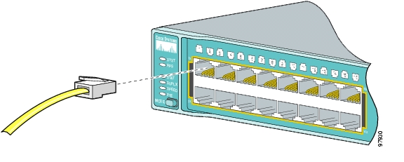
Figure 2-18 Connecting to an Ethernet Port
Connecting to SFP Modules
This section describes how to connect to SFP modules. For instructions on how to connect to fiber-optic SFP modules, see the "Connecting to Fiber-Optic SFP Modules" section. For instructions on how to connect to copper 1000BASE-T SFP modules, see the "Connecting to 1000BASE-T SFP Modules" section.
For instructions about how to install or remove an SFP module, see the "Installing and Removing SFP Modules" section.
Connecting to Fiber-Optic SFP Modules
Follow these steps to connect a fiber-optic cable to an SFP module:
Warning
Caution
Before connecting to the SFP module, be sure that you understand the port and cabling stipulations in the "Installation Guidelines" section and in the "SFP Module Slots" section on page 1-8. See Appendix B, "Connector and Cable Specifications," for information about the LC on the SFP module.
Step 1
Step 2
Step 3
Step 4
The LED turns green when the switch and the target device have an established link.
The LED turns amber while the STP discovers the network topology and searches for loops. This process takes about 30 seconds, and then the port LED turns green.
If the LED is off, the target device might not be turned on, there might be a cable problem, or there might be problem with the adapter installed in the target device. See Chapter 3, "Troubleshooting," for solutions to cabling problems.
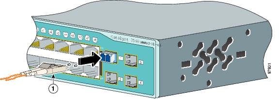
Figure 2-19 Connecting to a Fiber-Optic SFP Module Port
Step 5
Connecting to 1000BASE-T SFP Modules
Follow these steps to connect a Category 5 cable to a 1000BASE-T SFP module:
Caution
Step 1
Note
Note
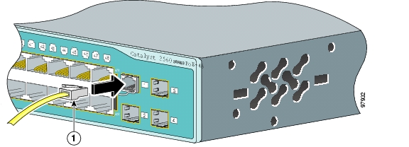
The Auto-MDIX feature is enabled by default on switches running Cisco IOS Release 12.2(18)SE or later. For releases between Cisco IOS Release 12.1(14)EA1 and 12.2(18)SE, the Auto-MDIX feature is disabled by default. For configuration information for this feature, see the switch software configuration guide or the switch command reference.Figure 2-20 Connecting to a 1000BASE-T SFP Module
Step 2
Step 3
The LED turns green when the switch and the target device have an established link.
The LED turns amber while the STP discovers the network topology and searches for loops. This process takes about 30 seconds, and then the port LED turns green.
If the LED is off, the target device might not be turned on, there might be a cable problem, or there might be problem with the adapter installed in the target device. See Chapter 3, "Troubleshooting," for solutions to cabling problems.
Step 4
Where to Go Next
If the default configuration is satisfactory, the switch does not need further configuration. You can use any of these management options to change the default configuration:
•
•
a.
You must be a registered Cisco.com user, but you need no other access privileges.
b.
c.
d.
See the Network Assistant online help and the getting started guide for more information.
•
For setup instructions that use the CLI setup program, go to Appendix C, "Configuring the Switch with the CLI-Based Setup Program."
•
![]()
![]()
![]()
![]()
![]()
![]()
![]()
![]()
Posted: Thu Apr 28 13:02:49 PDT 2005
All contents are Copyright © 1992--2005 Cisco Systems, Inc. All rights reserved.
Important Notices and Privacy Statement.