|
|

Table Of Contents
Product Overview
This chapter provides an overview of the features and components of the Catalyst 2948G, 2948G-GE-TX, and 2980G switches. It contains these sections:
Note
Throughout this guide, Catalyst 2980G switch refers to both the Catalyst 2980G switch and the Catalyst 2980G-A switch, unless otherwise noted.
Switch Description
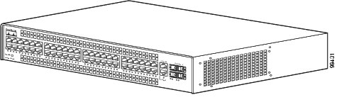
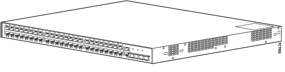
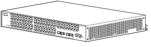
The Catalyst 2948G, 2948G-GE-TX, and 2980G switches are designed for high-performance, high-density wiring-closet applications. Figure 1-1 through Figure 1-3 show the switches.
Figure 1-1 Catalyst 2948G Switch
Figure 1-2 Catalyst 2948G-GE-TX Switch
Figure 1-3 Catalyst 2980G Switch
The Catalyst 2948G, 2948G-GE-TX, and 2980G switches interface with networking equipment using Ethernet (10BASE-T), Fast Ethernet (100BASE-T), and Gigabit Ethernet (1000BASE-T) interfaces. Depending on the model, the switches also support Gigabit Interface Converters (GBICs) or small form-factor pluggable (SFP) modules.
The Catalyst 2948G switch has 48 autosensing and autoconfiguring 10/100BASE-T Fast Ethernet fixed ports. The Catalyst 2948G-GE-TX switch has 48 autosensing and autoconfiguring 10/100/1000BASE-T ports. The Catalyst 2980G switch has 80 autosensing and autoconfiguring 10/100BASE-T Fast Ethernet fixed ports.
GBIC Module Support
The Catalyst 2948G and 2980G switches each have two Gigabit Ethernet uplink ports with modular Gigabit Interface Converters (GBICs).
A GBIC is a hot-swappable input/output device that plugs into a Gigabit Ethernet port module and links the port module with a fiber-optic network. For a detailed description of Gigabit Ethernet ports, see the "GBIC Features" section.
For a complete list of supported GBIC modules, see Table 4-1 on page 4-3.
Note
The Gigabit Ethernet ports can be configured with any combination of GBIC types.
The Gigabit Ethernet ports on these modules are used primarily for backbone interconnection of other high-performance switches and routers.
SFP Module Support
The Catalyst 2948G-GE-TX switch has four small form-factor pluggable (SFP) module slots. The switch uses SFP modules to establish Gigabit connections. The SFP module slots are located on the front of the switch.
An SFP module is a hot-swappable input/output device that plugs into an SFP module slot, linking the port module with a fiber-optic network.
For a list of SFP modules supported by the Catalyst 2948G-GE-TX switch, see Table 1 in the Release Notes for Catalyst 4500 Series Software Release 8.xGLX, located at this URL:
http://www.cisco.com/univercd/cc/td/doc/product/lan/cat4000/relnotes/ol_4502.htm#wp272673
Note
Except for the 1000BASE-T SFP module, all of the SFP modules are used to establish fiber-optic connections. You use fiber-optic cables with Lucent (LC) connectors to connect to an SFP module. The SFP modules support 850 to 1550 nanometer nominal wave lengths. These field-replaceable modules provide the uplink optical interfaces, laser send (TX) and laser receive (RX). For a detailed description of Gigabit Ethernet ports see the "Verifying Switch Operation" section.
Switch Features
Table 1-1 describes the Catalyst 2948G, 2948G-GE-TX, and 2980G switch features.
Table 1-1 Catalyst 2948G, 2948G-GE-TX, and 2980G Switch Features
Ethernet speeds
•
•
Note
•
Standard management and support
•
•
Standard management and support (continued)
•
•
Software management
•
•
•
•
Note
•
•
–
–
–
–
Embedded management
•
•
•
•
Power supplies
•
•
•
1 VTP = VLAN Trunking Protocol
2 PAgP = Port Aggregation Protocol
3 CLI = command-line interface
4 RMON = Remote Monitoring
5 CDP = Cisco Discovery Protocol
6 VTP = Virtual Terminal Protocol
7 CGMP = Cisco Group Management Protocol
Port Locations
This section describes the port locations and numbering on the switches.
10/100 and 10/100/1000 Ports
The 10/100 and 10/100/1000 ports are configured in vertical pairs. Each vertical pair has two Link Status LEDs below it. The LED on the left is for the top port; the LED on the right is for the bottom port. For example, LED 1 is for the upper port (port 1) and LED 2 is for the bottom port (port 2).
Catalyst 2948G and 2980G Switch Ports
The Catalyst 2948G switch 10/100BASE-T ports are configured in two rows. The top row contains odd-numbered ports (1 through 47), and the bottom row contains even-numbered ports (2 through 48).
The Catalyst 2980G switch 10/100BASE-T ports are configured in four rows. The top two rows are numbered 1 through 48, with the first row odd-numbered (1 through 47) and the second row even-numbered (2 through 48). The bottom two rows are numbered 1 through 32, with the first row odd-numbered (1 through 31) and the second row even-numbered (2 through 32).
Two GBIC ports are at the right of the front panel on the Catalyst 2948G and Catalyst 2980G switches:
•
•
Catalyst 2948G-GE-TX Switch Ports
The Catalyst 2948G-GE-TX 10/100/1000BASE-T Gigabit Ethernet ports are configured in two rows. The top row contains odd-numbered ports (1 through 47), and the bottom row contains even-numbered ports (2 through 48).
The SFP module slots are numbered left to right 49 through 52.
Switch Components
This section describes the following Catalyst 2948G and 2980G switch components:
•
Management Ports
The Catalyst 2948G, 2948G-GE-TX, and 2980G switches have two kinds of management ports: console serial and Ethernet. The Catalyst 2948G switches have a 10BASE-T management port. The Catalyst 2948G-GE-TX and 2980G-A switches have a 10/100BASE-T management port.
Table 1-2 lists the management options for the switches.
Console Serial Port
An RJ-45 console serial port allows you to perform switch-management functions using a terminal. See Table A-1 on page A-1 for the console connector pinouts.
10BASE-T and 10/100BASE-T Ports
An RJ-45 10BASE-T port allows you to perform TCP/IP switch-management functions (Telnet, SNMP, FTP), configure IP addresses with BOOTP, and download software images.
Note
This port is for network management only; it is not for switching. Connectivity is not available between this port and the 10/100BASE-T switching ports.
Front Panel LEDs
The LEDs on the front panels of the Catalyst 2948G, 2948G-GE-TX, and 2980G switches perform the following functions:
•
•
•
•
•
Table 1-2 describes the LEDs.
Airflow
Note
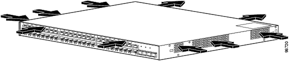
On the Catalyst 2948G and 2980G switches, the system fan assembly provides cooling air for the internal chassis components. The fans exhaust warm air from one end and draw in cool air at the other end.
If an individual fan fails, the other fans continue to run. Sensors monitor the internal air temperatures. If the air temperature exceeds a tolerable threshold, the environmental monitor displays warning messages.
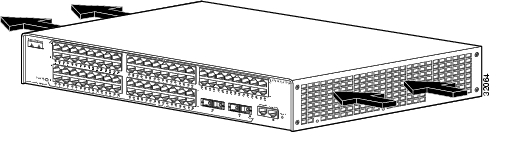
On the Catalyst 2948G-GE-TX, a blower system draws cool air in from the front and sides of the switch and exhausts air out the back.
Figure 1-4 shows the direction of airflow through the Catalyst 2948G switch.
Figure 1-5 shows the direction of airflow through the Catalyst 2948G-GE-TX switch.
Figure 1-6 shows the direction of airflow through the Catalyst 2980G switch.
Figure 1-4 Catalyst 2948G Airflow
Figure 1-5 Catalyst 2948G-GE-TX Airflow
Figure 1-6 Catalyst 2980G Airflow
Power Supplies
There is no power switch on the switches. AC power is present in the power supply when the power cord is plugged in.
The environmental monitoring and reporting functions allow you to maintain normal system operation by correcting adverse environmental conditions before loss of operation.
Each power supply monitors its own temperature and output voltages. If the power supply becomes excessively hot, it shuts down to prevent damage. The switches monitor the operating condition of the power supply and report the status using switch software.
The switches have the following power supplies:
•
•
•
•
Note
These switches also be used with an optional Cisco Redundant Power System (RPS).
•
The Cisco RPS 600 supports four external devices that use up to 150 W DC each. Use a one-to-one cable (one connector at each cable end) to connect four external devices to the four DC output power modules.
The power source is partially redundant. There are two AC input power modules for the Cisco RPS and one DC output power module for each external device. The AC input to the Cisco RPS is fully redundant, but the DC output to the external devices is not.
Warning
•
The RPS 675 supports six external network devices and provides DC power to one failed device at a time. It automatically senses when the internal power supply of a connected device fails and provides power to that device, which prevents loss of network traffic.
Warning
•
The RPS 300 supports six external network devices and provides power to one failed device at a time. It automatically senses when the power supply of a connected device fails and provides the necessary power to the failed device to prevent loss of network traffic. When the internal power supply of the device has been brought up or replaced, the RPS automatically stops powering the device.
Warning
A Cisco RPS can only power one switch at a time. If more than one switch fails at the same time, any subsequent switch is not supported by the RPS until the first switch failure is resolved. For more information, refer to the documentation that was included with your RPS.
On the Catalyst 2948G switch, you must use a Y cable to connect the switch to two RPS 600 power supplies. Each RPS 600 has status LEDs (PSI and RPS).
On the Catalyst 2980G-A switch, each RPS 300 power supply has an individual power cord and has status LEDs (PSI, PWR, and RPS).
The RPS uses redundant power supplies. If one of the power supplies in the RPS fails, the RPS will automatically switch over to the other power supply without forcing the switch to reboot.
Note
![]()
![]()
![]()
![]()
![]()
![]()
![]()
![]()
Posted: Mon Jul 25 07:45:49 PDT 2005
All contents are Copyright © 1992--2005 Cisco Systems, Inc. All rights reserved.
Important Notices and Privacy Statement.