|
|

This chapter describes how to install Catalyst 2926 and Catalyst 2926G series switches. For first-time installations, perform the procedures in the following sections in the order listed.
This section provides safety information that you should read and understand to ensure a safe switch installation.
Follow these guidelines to ensure your safety and protect the equipment. This list is not inclusive of all potentially hazardous situations that you may be exposed to as you install the switch, so be alert.
 | Warning Before working on equipment that is connected to power lines, remove jewelry (including rings, necklaces, and watches). Metal objects will heat up when connected to power and ground and can cause serious burns or weld the metal object to the terminals. |
Follow these basic guidelines when working with any electrical equipment:
 | Warning Do not work on the system or connect or disconnect cables during periods of lightning activity. |
Perform the following steps to check the contents of the shipping container:
Step 1 Check the contents of the accessories box against the Accessories Box Components Checklist and the packing slip. Verify that you received all listed equipment, which should include the following:
Step 2 Check the switch to ensure that the model shipped matches the model listed on the packing list.
Step 3 To begin installation, proceed to the section "Rack-Mounting the Switch."
A rack-mount kit is included for mounting either the Catalyst 2926 or Catalyst 2926G series switch in a standard 19-inch (48.3-centimeter) equipment rack. The equipment rack must meet the following criteria:
The rack-mount kit is not suitable for use with other racks, such as telco-type equipment racks, or those with obstructions (such as a power strip) that could impair access to switch.
 | Caution Before installing the chassis in a rack, read the "Safety Overview" section to familiarize yourself with the proper site and environmental conditions. Failure to read and follow these guidelines could lead to an unsuccessful installation and possible damage to the system and components. |
 | Warning To prevent bodily injury when mounting or servicing this unit in a rack, you must take special precautions to ensure that the system remains stable. The following guidelines are provided to ensure your safety: |
 | Warning To prevent overheating the switch, do not operate it in an area that exceeds the maximum recommended ambient temperature of 104ºF (40ºC). To prevent airflow restriction, allow at least 3 inches (7.6 centimeters) of clearance around the ventilation openings. |
Before rack-mounting the switch, ensure the following:
The following tools and equipment are required to install the chassis in a rack:
Follow these steps to rack-mount the switch:
Step 1 Prepare for installation as follows:
(a) Place the chassis on the floor or on a sturdy table as close as possible to the rack. Leave enough clearance to allow you to move around the chassis.
(b) Use a tape measure to measure the depth of the rack from the outside of the front mounting posts to the outside of the rear mounting strip. The depth must be at least 19.25 inches (48.9 centimeters) but not greater than 32 inches (81.3 centimeters).
(c) Measure the space between the inner edges of the left front and right front mounting posts to ensure that it is 17.75 inches (45.1 centimeters) wide. (The chassis is 17.25 inches [43.8 centimeters] wide and must fit between the mounting posts.)
(d) Open the rack-mount kit and refer to the component checklist in Table 4-1 to verify that all parts are included.
| Quantity | Part Description | Received |
|---|---|---|
2 | L brackets |
|
4 | M4 Phillips pan-head screws |
|
4 | 12-24 x 3/4-inch Phillips binder-head screws |
|
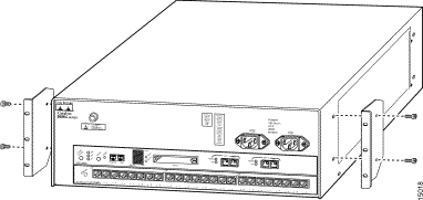
Step 2 Attach the left and right L brackets using the four M4 Phillips pan-head screws provided in the rack-mount kit (see Figure 4-1).
The L brackets and the mounting posts connect the chassis to the rack. You can mount the L brackets to the front or rear mounting posts of the chassis, depending on which end is in the front of the rack.

Step 3 Put on your ESD grounding strap and connect it to the chassis.
Step 4 Install the chassis in the rack as follows:
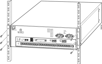
(a) Position the chassis in the rack as follows (see Figure 4-2):
If the chassis front panel is in the front of the rack, insert the rear of the chassis between the mounting posts.
If the rear of the chassis is in the front of the rack, insert the front of the chassis between the mounting posts.
(b) Align the mounting holes in the L bracket with the mounting holes in the equipment rack.
(c) Secure the chassis using six (three per side) 12-24 screws through the elongated holes in the L bracket and into the threaded holes in the mounting post.
(d) Use a tape measure and level to ensure that the chassis is installed straight and level.

Flash PC card slots on the front panel of the Catalyst 2926G series supervisor engine are for additional Flash PC card-based memory. You can use this Flash memory to store and run software images, configuration files, or to serve as an I/O device.
The Catalyst 2926G series supervisor engine has two Flash PC card slots: slot 0 (bottom) and slot 1 (top). The following procedure is generic and can be used for a Flash PC card in either slot position.
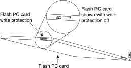
Before you install a Flash PC card, verify that the card is set with write protection off. The write-protect switch is located on the front edge of the card when oriented with the printing right side up and the edge connector end away from you. (See Figure 4-3.)

Use this procedure for installing and removing a Flash PC card from the Catalyst 2926G series switch:
Step 1 Face the front panel of the switch and hold the Flash PC card with the connector end of the card toward the slot. The connector end of the card is opposite the end with the write-protection switch, which is shown in Figure 4-3.
Step 2 Insert the card into the appropriate slot until the card completely seats in the connector at the back of the slot and the eject button pops out toward you. Note that the card does not insert all the way inside the slot; a portion of the card remains outside the slot. Do not attempt to force the card past this point.
Step 3 To eject a card, press the appropriate ejector button until the card is free of the connector at the back of the slot.
Step 4 Remove the card from the slot and place it in an antistatic bag.
Use the console port to connect a data terminal to your Catalyst 2926 and Catalyst 2926G series switches.
On the Catalyst 2926 series switch, the console port is located on the supervisor engine front panel and is labeled CONSOLE. (See Figure 4-4.)

The supervisor engine console port is a data communications equipment (DCE) DB-25 receptacle, which supports a DCE EIA/TIA-232 interface. EIA/TIA-232 supports unbalanced circuits at signal speeds up to 64 kbps.
Before connecting the console port, check the terminal documentation to determine the baud rate. The baud rate of the terminal must match the default baud rate (9600 bps) of the switch console port. Set up the terminal as follows:
Use a straight-through cable to connect the switch to a DTE device, such as a terminal or PC. Use a null-modem cable to connect the switch to a remote DCE device, such as a modem or data service unit (DSU). See Figure 4-5 for DCE and DTE cable connectors.

The console and AUX ports, located on the front panel of the Catalyst 2926G series switch, are shown in Figure 4-6.

The console port, which is an EIA/TIA-232 asynchronous serial port with an RJ-45 connector, is a full-featured DTE connection with hardware flow control.
Connect the terminal using a thin, flat, RJ-45-to-RJ-45 cable (looks like a telephone cable) and an RJ-45-to-DB-9, RJ-45-to-D-subminiature female, or RJ-45-to-D-subminiature male adapter.
This section provides port connection procedures for the Catalyst 2926 and Catalyst 2926G series switch supervisor engine uplink ports:
Interface cables and equipment, such as Ethernet transceivers, should already be in place. If necessary, see Chapter 3, "Site Planning," for specific requirements.
The 100BaseTX RJ-45 port cable connector is shown in Figure 4-7. The 100BaseTX MII cable connector is shown in Figure 4-8.


Use SC fiber-optic connectors (see Figure 4-9) to connect to the 100BaseFX, 1000BaseSX, and 1000BaseLX/LH ports. Always keep caps and plugs on the fiber-optic connectors on the cable and the switch when they are not in use.

Warning 
Because invisible laser radiation may be emitted from the aperture of the port when no cable is connected, avoid exposure to laser radiation and do not stare into open apertures.
On the Catalyst 2926 and Catalyst 2926G series switches, when all interfaces are connected, perform a final check of all connections. Then perform these steps to power on the system and verify that it is operational:
Step 1 Ensure the following before powering on the system:
(a) The switch power supply cords are not connected.
(b) All interface cable connections are secured.
(c) At the power-source end of the power cord, make sure the connectors are securely installed in grounded outlets and that the source power is within the range labeled on the back of the switch. Make sure that the power cord for the second power supply is connected to a separate line from the first, if possible.
Step 2 Check the console terminal and make sure it is on.
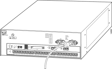
Step 3 Connect the power cords to the switch. See Figure 4-10.

Step 4 Verify that the appropriate PS1 and PS2 LEDs on the supervisor engine front panel are green.
Step 5 Listen for the system fans and check the fan LED on the supervisor engine. You should hear the fans begin to operate immediately.
Step 6 While the system initializes, check that the status LED on the supervisor engine is orange until the boot is complete.
Some interface LEDs might go on or blink for a short time. Some LEDs, such as the link LED, stay on during the entire boot process. If a port is already configured, the LEDs might be on steadily as they detect traffic on the line. Wait until the system boot is complete before attempting to verify the LEDs for the 10/100-Mbps Fast Ethernet autosensing switched ports.
When the system boot is complete (it takes a few seconds), the supervisor engine begins to initialize the 10/100-Mbps Fast Ethernet autosensing switched ports.
During this initialization, the LEDs on the 10/100-Mbps Fast Ethernet autosensing switched ports flash on and off. The STATUS LED goes on when initialization is complete, and the console screen displays a script and system banner.
Step 7 Your hardware installation is now complete. See Chapter 5, "Configuring the Switch," for default configuration information and commands to change the default configuration. Refer to the Software Configuration Guide and Command Reference for your switch for complete software configuration instructions.
![]()
![]()
![]()
![]()
![]()
![]()
![]()
![]()
Posted: Tue Dec 17 19:22:58 PST 2002
All contents are Copyright © 1992--2002 Cisco Systems, Inc. All rights reserved.
Important Notices and Privacy Statement.