|
|

This chapter describes how to prepare your site for installation of the Catalyst 2926 and Catalyst 2926G series switches. This chapter contains the following sections:
You should install your switch in an enclosed, secure area, ensuring that only qualified personnel have access to the switch and control of the environment. Equipment placed too close together or inadequately ventilated can cause system overtemperature conditions. In addition, poor equipment placement can make chassis panels inaccessible and difficult to maintain.
The switch operates as a standalone system mounted in a rack in a secure wiring closet. It requires a dry, clean, well-ventilated, and air-conditioned environment. The flow of ambient air must be maintained to ensure normal operation. If the airflow is blocked or restricted, or intake air is too warm, an overtemperature condition can occur. The switch's environmental monitor can then shut down the system to protect the system components.
To ensure normal operation and avoid unnecessary maintenance, plan your site configuration and prepare your site before installation. After installation, make sure the site maintains an ambient temperature of 0 to 40ºC (32 to 104ºF). It is essential to keep the area around the chassis as free from dust and foreign conductive material (such as metal flakes from nearby construction activity) as is possible. For a description of the environmental monitor and status levels, see the "Environmental Monitoring" section.
Multiple switches can be rack-mounted with little or no clearance above and below the chassis. However, when mounting a switch in a rack with other equipment, or when placing it on the floor near other equipment, ensure that the exhaust from other equipment does not blow into the intake vent of the chassis.
Cooling air is drawn in through the right side of the chassis. Keep the right side clear of obstructions, including dust and foreign conductive material, and away from the exhaust ports of other equipment.
Appendix A, "Technical Specifications," lists the operating and nonoperating environmental site requirements for the switches. To maintain normal operation and ensure high system availability, maintain an ambient temperature and clean power at your site. The environmental ranges listed in Appendix A are within the ranges that the switch will continue to operate; however, a measurement that approaches the minimum or maximum of a range indicates a potential problem. You can maintain normal operation by anticipating and correcting environmental anomalies before they exceed the maximum operating range.
 | Warning This unit is intended for installation in restricted access areas. A restricted access area is where access can only be gained by service personnel through the use of a special tool, lock and key, or other means of security, and is controlled by the authority responsible for the location. |
This section provides site power requirements. Verify your site power before you install the switch. This section consists of the following sections:
Follow these general requirements when preparing your site for the switch installation:
Follow these precautions when preparing your site for the switch installation:
 | Warning Ultimate disposal of this product should be handled according to all national laws and regulations. |
 | Warning Unplug the power cord before you work on a system that does not have an on/off switch. |
 | Warning Read the installation instructions before you connect the system to its power source. |
 | Warning This unit might have more than one power cord. To reduce the risk of electric shock, disconnect the two power supply cords before servicing the unit. |
 | Warning This product relies on the building's installation for short-circuit (overcurrent) protection. Ensure that a fuse or circuit breaker no larger than 120 VAC, 15A U.S. (240 VAC, 10A international) is used on the phase conductors (all current-carrying conductors). |
 | Warning This equipment is intended to be grounded. Ensure that the host is connected to earth ground during normal use. |
When setting up the plant wiring, consider the following factors:
This section provides estimates of the power requirements and heat dissipation for the Catalyst 2926 series switch (Catalyst 2926T switch and Catalyst 2926F switch) and Catalyst 2926G series switch (Catalyst 2926GS switch and Catalyst 2926GL switch). The power requirements might be useful for planning the power distribution system needed to support the switch. Heat dissipation is an important consideration for sizing the air conditioning requirements for an installation. The power and heat associated with a Catalyst 2926 series switch and Catalyst 2926G series switch varies upon the average switching traffic levels.
Unless otherwise noted, the information assumes worst-case conditions. Typical numbers are approximately 30 percent below the numbers listed here.
Table 3-1 lists the power requirements and heat dissipation estimates for the Catalyst 2926T switch, which is configured as follows:
| Model Number/ Card Type | AC Input Power (Watts) | Heat Diss. (BTU/HR) | Input Current at 90 VAC (Amps) | Input Current at 120 VAC (Amps) | Input Current at 180 VAC (Amps) | Input Current at 240 VAC (Amps) |
|---|---|---|---|---|---|---|
Catalyst 2926T chassis (with frame) | 42 | 144 | 0.47 | 0.35 | 0.23 | 0.18 |
Supervisor, UTP1 | 71 | 243 | 0.79 | 0.59 | 0.39 | 0.30 |
10/100-Mbps | 101 | 344 | 1.12 | 0.84 | 0.56 | 0.42 |
Total | 214 | 731 | 2.38 | 1.78 | 1.18 | 0.90 |
| 1UTP = unshielded twisted-pair |
Table 3-2 lists the power requirements and heat dissipation estimates for the Catalyst 2926F switch, which is configured as follows:
| Model Number/ Card Type | AC Input Power (Watts) | Heat Diss. (BTU/HR) | Input Current at 90 VAC (Amps) | Input Current at 120 VAC (Amps) | Input Current at 180 VAC (Amps) | Input Current at 240 VAC (Amps) |
|---|---|---|---|---|---|---|
Catalyst 2926F chassis (with fans) | 42 | 144 | 0.47 | 0.35 | 0.23 | 0.18 |
Supervisor, MMF1 | 62 | 212 | 0.69 | 0.52 | 0.34 | 0.26 |
10/100-Mbps | 101 | 344 | 1.12 | 0.84 | 0.56 | 0.42 |
Total | 205 | 700 | 2.28 | 1.71 | 1.13 | 0.86 |
| 1MMF = multimode fiber |
Table 3-3 lists the power requirements and heat dissipation estimates for the
Catalyst 2926G series switch, which is configured as follows:
| Model Number | AC Input Power (Watts) | Heat Diss. (BTU/HR) | Input Current at 90 VAC (Amps) | Input Current at 120 VAC (Amps) | Input Current at 180 VAC (Amps) | Input Current at 240 VAC (Amps) |
|---|---|---|---|---|---|---|
Catalyst 2926G | 260 | 888 | 2.89 | 2.17 | 1.44 | 1.09 |
This section provides cabling guidelines for your networks using the Catalyst 2926 and Catalyst 2926G series switches. This section also describes connection equipment you will need to connect to network devices.
When preparing your site for cabling to the switch, you need to consider several factors for each switch interface type. Use the following sections to determine your cabling requirements:
Before installing the switch, have all cables and any additional interface equipment on hand. If you intend to build your own cables, refer to the cable pinouts in Appendix B, "Cabling Specifications."
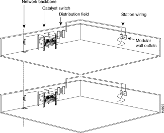
The network cabling components shown in Figure 3-1 consist of the following:

The length of your networks and the distances between connections depend on the type of signal, the signal speed, and the transmission media (the type of cabling used to transmit the signals). The distance and rate limits in the following sections are the IEEE-recommended maximum speeds and distances for signaling.
The distance limits in the following sections are provided as guidelines for planning your network connections before installation.
The maximum distances for Fast Ethernet network segments and connections (shown in Table 3-4) depend on the type of transmission cable used. The term 10BaseT is an abbreviation for 10 Mbps transmission, Baseband medium, and T for twisted pair.
| Transceiver Speed | Cable Type | Duplex Mode | Maximum Distance between Stations |
|---|---|---|---|
10/100 Mbps | Category 5 UTP | Full and half | 328 ft (100 m) |
100 Mbps | Multimode fiber | Full | 1.2 miles (2 km) |
100 Mbps | Multimode fiber | Half | 1312 ft (400 m) |
Table 3-5 provides cabling specifications for the Gigabit Ethernet uplink ports on
Catalyst 2926G series switches. All Gigabit Ethernet uplink ports have SC-type connectors, and the minimum cable distance for both types listed (MMF and SMF) is 6.5 feet (2 meters).
| Gigabit Ethernet Uplink | Wavelength (nm) | Fiber Type | Core Size (micron) | Modal Bandwidth (MHz.km) | Cable Distance |
|---|---|---|---|---|---|
SX1 | 850 | MMF
| 62.5 62.5 50.0 50.0 | 160 200 400 500 | 722 ft (220 m) 902 ft (275 m) 1640 ft (500 m) 1804 ft (550 m) |
LX/LH | 1300 | MMF2
SMF (LX/LH) | 62.5 50.0 50.0 9/10 | 500 400 500 - | 1804 ft (550 m) 1804 ft (550 m) 1804 ft (550 m) 32,810 feet (10 km) |
| 1MMF only. 2Patch cord recommended. See the "Connecting the Patch Cord (Catalyst 2926GL Switch Only)" section for details. |
When connecting the 1000BaseLX/LH uplink port with 62.5-micron diameter multimode fiber (MMF), we recommend you install a mode-conditioning patch cord (Cisco product number CAB-GELX-625 or equivalent) between the uplink port and the MMF cable on both the transmit and receive ends of the link. The patch cord is required for link distances greater than 984 feet (300 meters). Otherwise, an effect called Differential Mode Delay might degrade link performance. For more information, refer to Appendix E, "Differential Mode Delay."
Figure 3-2 shows a typical configuration using the patch cord.

Plug the end of the patch cord labeled "To Equipment" into the uplink port (see Figure 3-3). Plug the end labeled "To Cable Plant" into the patch panel.

The maximum distances for fiber-optic network connections are determined by the transmitter output power, receiver sensitivity, and type of optical source, as shown in Table 3-6.
| Item | Description |
|---|---|
Transmitter Output Power | -19 to -14 dBm |
Receiver Sensitivity | -32.5 to -14 dBm |
Wavelength | 1270 to 1380 nm |
Optical Source | LED |
Maximum Span | 1.2 miles (2 km) |
As with all signaling systems, serial signals can travel a limited distance at any given bit rate; generally, the slower the baud rate, the greater the distance. Table 3-7 shows the standard relationship between baud rate and distance for EIA/TIA-232 signals.
| Rate (bps) | Distance (Feet) | Distance (Meters) |
|---|---|---|
2400 | 200 | 60 |
4800 | 100 | 30 |
9600 | 50 | 15 |
19,200 | 25 | 7.6 |
38,400 | 12 | 3.7 |
56,000 | 8.6 | 2.6 |
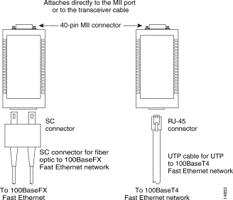
Ethernet transceivers are available from a variety of sources for Virtual Terminal Protocol (VTP) and multimode fiber-optic cabling. Figure 3-4 shows an example of Fast Ethernet and Gigabit Ethernet transceivers and connection equipment.
You might need additional data communications equipment to complete your installation.
When planning your connections, consider the types and locations of connectors on adjacent switching ports to avoid overlapping the transceiver and impairing access to other connections.

Table 3-8 lists the site planning activities that you should perform before you install the switch. Completing each activity helps ensure a successful switch installation.
| Task No. | Planning Activity | Verified By | Time | Date |
|---|---|---|---|---|
1 | Space Evaluation: Space and layout |
|
|
|
2 | Environmental Evaluation: Ambient temperature |
|
|
|
3 | Power Evaluation: Input power type |
|
|
|
4 | Grounding Evaluation: Circuit breaker size |
|
|
|
5 | Cable and Interface Equipment Evaluation: Cable type |
|
|
|
6 | EMI Evaluation: Distance limitations for signaling |
|
|
|
![]()
![]()
![]()
![]()
![]()
![]()
![]()
![]()
Posted: Thu Jul 1 13:18:36 PDT 1999
Copyright 1989-1999©Cisco Systems Inc.