|
|

This chapter describes the cabling requirements and other preinstallation guidelines for installing an EtherSwitch 1420 or EtherSwitch 1220. Several sample configurations are also included.
You can install your EtherSwitch 1420 or 1220 in the same locations as your other Ethernet hubs, bridges, and routers. This would normally be a wiring closet but it could also be an office.
The switch can be mounted on a table, shelf, or rack. The key requirement is that it be located within 100 meters of its attached 10BaseT devices. As most of the LEDs and the cable connectors are on the front panel, you should ensure easy access to the front of the switch. Avoid routing any UTP cabling used to connect to switch ports near power lines, fluorescent lights, or other sources of electrical noise.
The EtherSwitch 1420 and EtherSwitch 1220 are compatible with the IEEE 802.3 CSMA/CD media access control layer and frame format. They therefore support existing network management software and diagnostic tools.
The 10BaseT ports are compatible with the IEEE 802.3 10BaseT standard and connect to individual workstations, 10BaseT hubs, or other 10BaseT compatible devices. The 100BaseTX ports are compatible with the IEEE 802.3u 100BaseTX specification and connect to 100BaseTX servers, hubs, backbone switches, and routers.
The high-speed expansion slots support the modules described in the EtherSwitch 1420 Modules Installation Guide.
Each type of EtherSwitch 1420 or 1220 port has its own cabling guidelines. These include the kinds of devices you can connect to the ports and the length and type of wiring you can use.
Use a straight-through cable to connect to a device not marked with an X, such as a server or workstation. Use a crossover cable to connect to a port marked with an X, such as another EtherSwitch 1420, an EtherSwitch 1220, or other 100BaseTX compatible hub, switch, or router. Pinouts for these cables are described in "Connector Pinouts" in
Appendix A, "Technical Specifications."
The 24 10BaseT ports require Category 3, 4, or 5 UTP wiring. Attached devices must be within 100 meters of the switch and be 10BaseT-compatible.
Port 25 is an AUI connector and connects to an external thick coaxial, thin coaxial, or fiber-optic transceiver. Supported network and device distances will vary depending on the type of transceiver used.
The two 100BaseTX ports require Category 5 UTP cabling. Attached devices must be within 100 meters of the port and be 100BaseTX-compatible.
Configuration and cabling guidelines for the modules that you can insert in the high-speed expansion slots are described in the EtherSwitch 1420 Modules Installation Guide.
This section describes several situations where the EtherSwitch 1420 or 1220 can be used in your network. The following scenarios are covered:
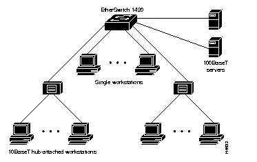
The EtherSwitch 1420 or 1220 supports 25 switched Ethernet connections for single workstations or 10BaseT hubs. Two 100BaseTX modules (EtherSwitch 1420) or two fixed 100BaseTX ports (EtherSwitch 1220) are used to connect to servers, as shown in Figure 2-1.
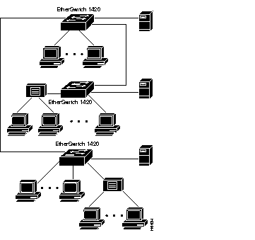
Multiple EtherSwitch 1420s or 1220s can be daisy-chained via full-duplex 100BaseT for up to 200-Mbps bandwidth between switches. Additional high-speed ports using single or multiport EtherSwitch 1420 repeater modules can be used to connect to 100BaseT servers or other devices. Figure 2-2 is an example of such a configuration.
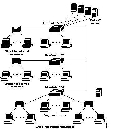
Multiple EtherSwitch 1420s or 1220s can be connected via shared 100BaseT using a multiport repeater in an EtherSwitch 1420. More high-speed server connections can be added by using additional EtherSwitch 1420 modules, as shown in Figure 2-3.
EtherSwitch 1420s and 1220s can connect to a 100BaseT backbone switch or router, as shown in Figure 2-4. With support for full-duplex operation, each 100BaseT link supports up to 200 Mbps of bandwidth and fiber-optic cabling distances of up to 2 kilometers.
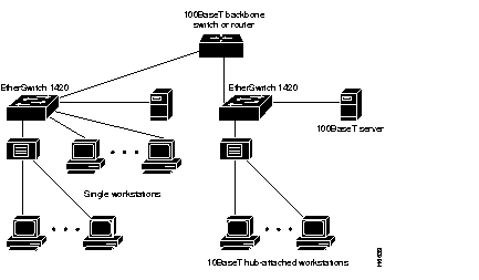
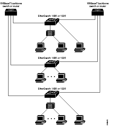
Figure 2-5 shows EtherSwitch 1420s connecting to a 100BaseT backbone switch or router in a redundant backbone configuration, using the Spanning-Tree Protocol. With support for full-duplex operation, each 100BaseT link supports up to 200 Mbps of bandwidth and fiber-optic cabling distances of up to 2 kilometers.
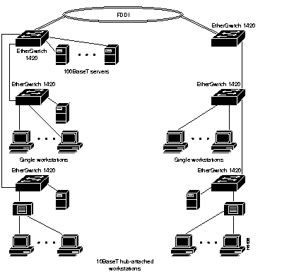
FDDI backbone connectivity can be provided by an EtherSwitch 1420 with an FDDI module. EtherSwitch 1420 FDDI modules support UTP single-attachment station (SAS), fiber-optic SAS, and fiber-optic dual-attachment station (DAS) configurations for connecting to servers, routers, concentrators, or direct ring attachment, as shown in Figure 2-6.
|
|