|
|

This chapter explains the concepts listed below that you'll need to understand to effectively configure and manage your EtherSwitch 1420 or 1220:
With multiple Media Access Control (MAC) address support on all ports, you can connect individual workstations, repeaters, switches, routers, or other network devices to any switch port.
The EtherSwitch 1420 and 1220 maintain an address table associating the address of each device with the port on which it resides.
The EtherSwitch 1420 and 1220 can automatically learn the source address of packets that are received on each port. The switch then adds these dynamic addresses and associated port numbers to the address table. As stations are added or removed from the network, the switch automatically updates the address table by adding new entries and aging out ones currently not in use. Dynamic addressing simplifies the management of the switch and requires no configuration.
A network administrator can also manually enter addresses into the address table. These static addresses do not age and must be added or removed by the administrator. Static addressing also allows for a measure of security in that access to a port can be restricted. See the "Securing Ports" section in this chapter for more information.
EtherSwitch 1420s and 1220s forward, filter, and flood packets in accordance with the IEEE 802.1d specification. Each switch transfers, or forwards, packets between any combination of ports based on the destination address of the received packet. By maintaining an address table that determines which port the address resides on, the switch is able to forward the packet only to that port. If the destination address resides on the port the packet was received from, the packet is filtered and not forwarded.
If a destination address is not known by the switch, it sends (floods) the packet to all ports. This ensures that the packet will arrive at its destination even when the switch does not know on which port the destination address resides. The EtherSwitch 1420 and 1220 can also flood multicast and broadcast packets. There are times when it can be useful to disable flooding. See the "Flooding Controls" section in this chapter for more information.
The EtherSwitch 1420 and 1220 also support source-port filtering. This enhanced filtering capability only forwards packets to destinations when received on specified ports. Packets to these destinations received on other ports are filtered. These destinations are referred to as restricted static addresses. See the "Port Addressing" section in the "Out-of-Band Management" chapter for more information. If you are using SNMP, see the "Standard MIBs and MIB Extensions" section in the "In-Band Management" chapter.
The switching mode determines how quickly the EtherSwitch 1420 and 1220 can forward a packet and, therefore, how much latency the packet will experience. Latency is the delay between the time a packet is received on one port and the time it is transmitted from the appropriate destination port. Selecting a switching mode is often a choice between enhanced error checking and lower latency.
The EtherSwitch 1420 and 1220 offer three switching modes:
FastForward and FragmentFree are two forms of cut-through switching. You can define the switching mode on the System Menu of the management console, as described in the "System Configuration" section of the "Out-of-Band Management" chapter. You can also use the appropriate MIB objects listed in the "Standard MIBs and MIB Extensions" section of the "In-Band Management" chapter.
FastForward offers the lowest level of latency by immediately forwarding a packet after receiving the destination address. Because FastForward starts forwarding before the entire packet is received, there can be times when packets are relayed with errors. Although the destination network adapter discards the faulty packet upon receipt, the superfluous traffic can be deemed unacceptable. Packets forwarded with errors can be reduced by using the FragmentFree option. In FastForward mode, latency is measured first-bit-received to first-bit-transmitted or FIFO.
FragmentFree switching filters out collision fragments, the majority of packet errors, before forwarding begins. In a properly functioning network, collision fragments must be less than 64 bytes. Anything greater than 64 bytes is a valid packet and is usually received without error. FragmentFree switching waits until the received packet has been determined not to be a collision fragment before forwarding the packet. In FragmentFree mode, latency is measured as FIFO.
The third switching mode supported by the EtherSwitch 1420 and 1220 is the traditional Store-and-Forward mode. Complete packets are stored and checked for errors prior to transmission. In Store-and-Forward mode, latency is measured last-bit-received to first-bit-transmitted or LIFO. This does not include the time it takes to receive the entire packet, which can vary, according to packet size, from 65 microseconds to 1.3 milliseconds. Store-and-Forward is the most error-free form of switching, but the forwarding latency is higher than either of the two cut-through switching modes, as shown in Table 3-1.
| Switching Mode | 10 Mbps to 10 Mbps | 10 Mbps to 100 Mbps | 100 Mbps to 100 Mbps | 100 Mbps to 10 Mbps |
|---|---|---|---|---|
| FastForward (FIFO)1 | 31 microsec | - | 7 microsec | 7 microsec |
| FragmentFree (FIFO) | 70 microsec | - | 9 microsec | 10 microsec |
| Store-and-Forward (LIFO)2 | 7 microsec | 7 microsec | 3 microsec | 3 microsec |
FastForward is the default switching mode and provides the lowest latency packet switching. If your attached networks experience a significant number of collisions, you can use FragmentFree to eliminate the chance of forwarding collision fragments. If you are experiencing frame check sequence (FCS) or alignment errors, use Store-and-Forward to ensure that packets with errors are filtered and not propagated to the rest of the network.
You select a switching mode for the entire switch; the chosen switching mode is then applied to traffic flowing between all ports with the following exceptions:
To define the switching mode with the management console, refer to the "System Configuration" section of the "Out-of-Band Management" chapter for more information. You can also define the switching mode in-band using any SNMP-compatible management station. Refer to the EtherSwitch 1420 and EtherSwitch 1220 MIB Reference Manual for a description of the appropriate MIB objects. The switching mode is set with the MIB objects listed in Table 6-1 in the "In-Band Management" chapter.
Secured ports restrict the use of a port to a user-defined group of stations. The number of devices on a secured port can range from 1 to 132. The addresses for the devices on a secure port are statically assigned by an administrator or sticky-learned. Sticky learning takes place when the address table for a port that is set as secured does not contain a full complement of static addresses. The port sticky-learns the source address of incoming packets and automatically assigns them as static addresses.
Secured ports generate address-security violations under the following conditions:
When a security violation occurs, the port can be suspended or disabled, as described in the "Port Status" section in this chapter, and SNMP traps can be generated. You can also choose to ignore the violation and keep the port enabled. What action is taken by the
switch is defined by the administrator using the MIB objects listed in Table 6-1 in the "In-Band Management" chapter or with the menu described in the "System Configuration" section in the "Out-of-Band Management" chapter.
There are several reasons to secure ports. Address security can be used to ensure that only members of a workgroup have access to the switch on a given port. When you assign static addresses to a secure port, the switch does not forward any packets with source addresses outside the group. Secured ports used in conjunction with VLANs allow for a completely secure switch.
The private Ethernet configuration is also an application of secured ports. If you define the address table of a secure port to contain only one address, the workstation or server attached to that port is guaranteed the full bandwidth of the port.
See the "Port Addressing" section in the "Out-of-Band Management" chapter for more on securing ports with the management console. If you are using SNMP, Table 6-1 in the "In-Band Management" chapter lists the MIB objects used for securing ports.
Port status is a system-wide indicator of the state of a port. The status of a port can change in response to security violations, by management intervention, or by actions of the Spanning-Tree Protocol. At any given time, each switch port will be in one of three states:
No packets are forwarded to or from a disabled or suspended port. However, suspended ports do monitor incoming packets to look for an activating condition. If a linkbeat returns, for example, a port suspended due to linkbeat failure returns to the enabled state.
You can configure an EtherSwitch 1420 or EtherSwitch 1220 to provide full-duplex operation on switched 100BaseT ports for up to 200 Mbps of bandwidth. Full duplex is the simultaneous transmission and reception of 100-Mbps streams.
A likely full-duplex scenario would be to connect a 100BaseT port to a server with a 100BaseT adapter configured for full duplex. You could also connect it to another switch configured for full duplex operation. 100BaseFX full-duplex links can span distances of up to 2 km.
See the "Port Configuration" section in the "Out-of-Band Management" chapter for instructions on configuring ports for full duplex. If you are using SNMP, Table 6-1 in the "In-Band Management" chapter lists the MIB objects required to configure full-duplex operation.
The design of the EtherSwitch 1420 and 1220 has the added security feature of precluding eavesdropping or monitoring of traffic destined for other ports. There are times, however, when you will want to use a Remote Monitoring (RMON) probe or sniffer to troubleshoot network problems by examining traffic on some or all of the switch's ports. Port-monitoring mode is provided for this purpose.
Port-monitoring mode forwards frames received from ports that are assigned to a capture list and forwards them to the port designated as the monitor port. This list can include any number of ports, from none to all 27. To enable port-monitoring mode with the management console, see the "Monitoring Configuration" section in the "Out-of-Band Management" chapter. If you are using SNMP, the MIB objects for configuring port monitoring are listed in Table 6-1 in the "In-Band Management" chapter.
Flooding is the forwarding of broadcast, multicast, and unicast packets with unknown destination addresses to all ports. In certain applications, this flooding might be unnecessary and undesirable. Note that when you create a VLAN, all traffic--including broadcast traffic--is kept within the boundaries of the VLAN, regardless of whether flooding controls are used.
When an EtherSwitch 1420 or 1220 receives a unicast packet with a destination address that it has not learned, the default is to flood it to all ports. However, on ports with only statically assigned addresses or single stations attached, there are no unknown destinations and flooding would serve no purpose. You can disable flooding in this case on a per-port basis. See the "Port Addressing" section in the "Out-of-Band Management" chapter for more information on disabling the flooding of packets with the management console. If you are using SNMP, the MIB objects for configuring this function are listed in Table 6-1 in the "In-Band Management" chapter.
When an EtherSwitch 1420 or 1220 receives a multicast or broadcast packet, the default is to flood it to all ports. You can use the switch's management console or SNMP to register multicast addresses and list the ports these packets are to be forwarded to. You can also disable the normal flooding of unregistered multicast packets on a per-port basis. Besides reducing unnecessary traffic, these features open up the possibility of using multicast packets for dedicated groupcast applications such as broadcast video. See the "Multicast Registration" section in the "Out-of-Band Management" chapter for more information about registering multicast addresses with the management console. If you are using SNMP, the MIB objects for configuring this function are listed in Table 6-1 in the "In-Band Management" chapter.
A broadcast storm is an increase in the number of broadcast packets coming from a given port. Forwarding these packets can cause the network to slow down or time out. To avoid this, broadcast storm control enables you to set a threshold for the number of broadcast packets that can be received from a port before forwarding is blocked. A second threshold is defined to determine when to re-enable the normal forwarding of broadcast packets.
The EtherSwitch 1420 and 1220 support up to four intraswitch VLANs. This capability allows ports on the switch to be grouped into separate logical networks. Unicast, broadcast, and multicast packets are forwarded (and flooded) only to those stations within a VLAN, creating a virtual firewall between VLANs. A port can be assigned to a VLAN using the switch's management console or in-band using any SNMP-compatible management station.
Because a VLAN is considered a separate logical network, it contains its own bridge MIB information and supports its own implementation of some of the features described in this section, including Spanning-Tree Protocol.
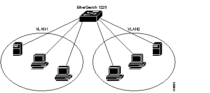
Figure 3-1 illustrates a simple VLAN configuration that groups workstations attached to an EtherSwitch 1220, ports 1 through 12, and a server attached to port A, into VLAN1. Workstations attached to ports 13 through 24 are grouped with a server attached to port B into VLAN2. The traffic on one VLAN is completely isolated from the traffic of the other.
See the "Virtual LAN Configuration" section in the "Out-of-Band Management" chapter for details on assigning ports to VLANs. If you are using SNMP, the MIB objects for configuring this function are listed in Table 6-1 in the "In-Band Management" chapter.
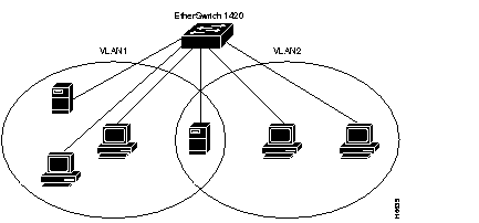
The EtherSwitch 1420 and 1220 support overlapping VLANs so resources can be shared between logical workgroups. Figure 3-2 shows two VLANs, VLAN1 and VLAN2, sharing a server connected to port A. Stations in both VLAN1 and VLAN2 can access the server, but are otherwise completely isolated from each other.
 | Caution Spanning-Tree Protocol might not prevent network loops in overlapping VLANs if the VLANs are connected in other ways besides the overlapping port. |
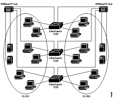
VLANs spanning multiple EtherSwitch 1420s or 1220s require a dedicated port on each switch for each VLAN interconnection. The configuration in Figure 3-3 shows two VLANs spanning multiple EtherSwitch 1220s. In this example, ports A and B on each switch provide the link to interconnect VLAN1 and VLAN2, respectively. An external 100BaseT hub (or FDDI concentrator) then connects each link to form the overall VLAN. If one or more of the switched 100BaseT ports on the EtherSwitch 1220 are used for other connections, or if more than two VLANs span multiple EtherSwitch 1220s, then a dedicated 10BaseT port on each switch is required to interconnect the VLAN.
Spanning-Tree Protocol is a standardized mechanism for maintaining a network of multiple bridges or switches. As part of the IEEE 802.1d standard, Spanning-Tree Protocol interoperates with compliant bridges and switches from other vendors. It transparently reconfigures bridges when the topology changes to avoid the creation of loops and to establish redundant paths in the event of lost connections. All 27 ports are included in EtherSwitch 1420 and 1220 Spanning-Tree Protocol support, and management of Spanning-Tree Protocol is through the standard bridge MIB.
You can create a redundant backbone with Spanning-Tree Protocol by connecting two switch ports to another device or to two different devices. Spanning-Tree Protocol will automatically disable one port but enable it if the other port is lost. If one link is high-speed and the other low-speed, the low-speed link is always disabled. If the speed of the two links is the same, the port priority and port ID are added together, and the link with the lowest value is disabled.
Dynamic addresses are aged and dropped from the address table after a configurable period of time.The default for aging dynamic addresses is 5 minutes. A reconfiguration of the spanning tree, however, can cause many station locations to change. Because this could mean that many stations were unreachable for 5 minutes or more, the address-aging time is accelerated so that station addresses can be dropped from the address table and then relearned. The accelerated aging is the same as the forward-delay parameter value when Spanning-Tree Protocol reconfigures. This parameter is described in the "Spanning-Tree Configuration" section in the "Out-of-Band Management" chapter. If you are using SNMP, Table 6-3 in the "In-Band Management" chapter lists the MIB objects used to configure this function.
|
|