|
|

This appendix describes the technical specifications and connector pinouts of the switch.
Table A-1 provides the technical specifications of both switches.
This section describes the following connectors used by the switch:
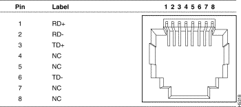
Ports 1 through 25 use standard RJ-45 connectors and 10BaseT pinouts with internal crossover, as indicated by an X. These 10BaseT ports have their transmit (TD) and receive (RD) signals internally crossed, for attachment of an adapter using a straight-through cable. Figure A-1 shows the connector pinout and the pin arrangement.

100BaseTX ports use an RJ-45 connector and pinout equivalent to the one shown in Figure A-1.
The AUI connector is a 15-pin female receptacle, as shown in Figure A-2; the pinout is shown in Table A-2.

| Pin | Label | Description |
| 1 | GND | Ground |
| 2 | CI+ | Positive AUI differential collision-data input |
| 3 | TX+ | Positive AUI differential transmit-data input |
| 4 | GND | Ground |
| 5 | RX+ | Positive AUI differential receive-data output |
| 6 | GND | Ground |
| 7 | NC | |
| 8 | GND | Ground |
| 9 | CI- | Negative AUI differential collision data |
| 10 | TX- | Negative AUI differential transmit-data input |
| 11 | GND | Ground |
| 12 | RX- | Negative AUI differential receive-data output |
| 13 | +12V | 12V supply for external MAU |
| 14 | GND | Ground |
| 15 | NC |
The serial connector is a male 9-pin D-Sub connector, as shown in Figure A-3. The pinout is shown in Table A-3.

| Pin | Label |
| 1 | DCD |
| 2 | RD |
| 3 | TD |
| 4 | DTR |
| 5 | GND |
| 6 | DSR |
| 7 | RTS |
| 8 | CTS |
| 9 | RI |
The shell is connected to the chassis ground. Use a standard modem cable to connect to a modem. Use a null-modem cable to connect to a terminal.
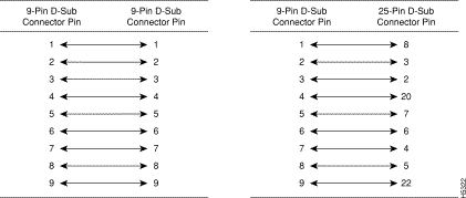
Either piece of equipment can come with either 9- or 25-pin connectors, as shown in Figure A-4 and Figure A-5.


The schematics of crossover and straight-through cables are shown in Figure A-6 and Figure A-7, respectively.


|
|