|
|

This chapter explains the basic tasks for configuring a multi-service, extranet Virtual Private Network (VPN) between a Cisco Secure VPN Client (VPN Client) and a Cisco IOS networking device (gateway). This case study describes IP Security Protocol (IPSec) tunnelling. This chapter includes the following sections:
 |
Note Throughout this chapter, there are numerous configuration examples that include unusable IP addresses, passwords, and public key examples. Be sure to use your own IP addresses, passwords, and public keys when configuring your VPN Clients and gateway. |
This case study describes how an enterprise plans, designs, and implements remote access VPNs using IPSec tunneling protocol. IPSec tunneling protocol authenticates and encrypts point-to-point (PPP) sessions from one device to another across a shared network infrastructure. This case study describes how a VPN Client is authenticated and encrypts an IPSec tunnel to the corporate enterprise. This case study contains following topics:
This section includes the following topics:
IPSec tunneling protocol is based on the IPSec Security Protocol feature, which is framework of open standards developed by the Internet Engineering Task Force (IETF). IPSec provides data confidentiality, data integrity, and data authentication between participating peers. IPSec provides these security services at the IP layer; it uses IKE to handle negotiation of protocols and algorithms based on local policy and to generate the encryption and authentication keys to be used by IPSec. IPSec can be used to protect one or more data flows between a pair of hosts, between a pair of security gateways, or between a security gateway and a host.
In IPSec tunnel mode, the remote users' VPN Clients encrypt the entire original IP datagrams. These encryptions become the payload in new IP packets. The VPN Clients initiate IPSec tunnels with a network device, such as a Cisco IOS router or a Cisco Secure PIX Firewall (gateway). The gateway acts as an IPSec proxy, performing encryption on behalf of all the hosts. The VPN Clients encrypt packets and forward them along the IPSec tunnel. The gateway decrypts the original IP datagrams and forwards them to their destination.
The major advantage of IPSec tunnel mode is that the end systems do not need to be modified to receive the benefits of IPSec. IPSec tunnel mode also protects against traffic analysis; with IPSec tunnel mode an attacker can only determine the tunnel endpoints and not the true source and destination of the tunneled packets, even if they are the same as the tunnel endpoints.
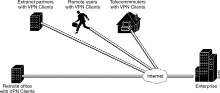
Figure 2-1 shows an enterprise with a specific business objective. The enterprise must provide secured access to multiple remote users (such as telecommuters, travelling remote users, remote offices, and extranet partners). To do this, remote users use VPN Clients to authenticate a connection to the corporate internal network, then to encrypt tunnels for data to the corporate internal network using IPSec tunneling protocol.
For the enterprise, there are several business considerations when configuring Layer 3 Encryption:
These considerations affect the overall VPN architecture of the enterprise network. Based on the features you choose to configure your VPN network, your network will be more or less secure and scalable. This section provides a brief introduction of the encryption features, their limitations and restrictions, and their role in a VPN solution. Depending on your network topology, one or more of the following encryption features may be a requirement in your VPN network.
|
Note For information about which features are supported on a specific Cisco IOS software release or version of the VPN Client, refer to the release notes for your version of the VPN Client. For more details, refer to "Cisco Secure VPN Client Documentation" in the Preface. |
This section includes the following topics:
The manual configuration feature addresses the enterprise requirement to allow for a more secure method of assigning IP addresses to a small number of VPN Clients by assigning static internal IP addresses. A static IP address is a unique IP address that is assigned to a client for an extended period of time, to be used by only that client.
Without the manual configuration feature, it is difficult for the gateway to authenticate a VPN Client with an IP address dynamically-assigned through an ISP. A local ISP assigns the VPN Client a routable IP address from its pool. The VPN Client creates an encrypted tunnel to the gateway. The tunnel source IP address, which is the IP address of the client as the IPSec peer, matches the original source IP address, which is the IP address assigned to the client by the ISP for communications with the ISP. Because both source IP addresses match, the gateway cannot determine which source IP address belongs to the trusted peer.
For an enterprise with a small number of VPN Clients, manual configuration is a simple method of assigning internal corporate IP addresses to each remote VPN Client, making it easier to set up IPSec policy on each VPN Client. IKE Mode Configuration is the alternative to manually configuring internal IP addresses on each remote access VPN Client.
For a large number of VPN Clients, manual configuration is not a very secure method. The IP address on the VPN Client is static, and remains configured on the VPN Client even when a remote user is not logged on. The static IP address or IKE security parameters on the VPN Client can be viewed, then used by an untrusting party. The untrusting party can masquerade as the remote user. For this reason, manual configuration is less secure than IKE Mode Configuration in that it is more sensitive to IP spoofing attacks. Should an attacker get access to the IKE security parameters on a VPN Client, that attacker can masquerade as the remote user authorized to connect to the corporate network.
For a large number of VPN Clients, manual configuration is also not very scalable because each VPN Client must be manually configured. Each time the network grows, configuring and maintaining additional VPN Clients can be time-consuming and complex. Each time the gateway is reconfigured to permit access to more VPN Clients, each VPN Client has to be reconfigured to match the new gateway configuration.
To prevent attacks, the following instructions should be a part of your enterprise security policy:
The alternative to static IP addressing with manual configuration is dynamic IP addressing with IKE Mode Configuration.
This section includes the following topics:
The IKE Mode Configuration feature addresses the enterprise requirement to issue scalable, dynamic IP addresses to one or more clients by configuring scalable IPSec policy on the gateway. A dynamic IP address is an IP address that is temporarily assigned as part of a login session, to be returned to an IP pool at the end of the session. IKE Mode Configuration is a gateway-initiated IKE negotiation that occurs between IKE phase 1 and IKE phase 2. The gateway assigns a dynamic IP address to the VPN Clients, replacing any current IP address configuration on the VPN Clients. IKE Mode Configuration secures the connection between the VPN Clients and ISPs with an IPSec tunnel, and allows for dynamic IP addressing of VPN Clients from the gateway. With IKE Mode Configuration, you can download IP addresses (and other network level configuration, such as your IPSec policy) to VPN Clients as part of an IKE negotiation. The gateway administrator can add VPN Clients to the network without having to reconfigure the gateway or the VPN clients.
Without the IKE Mode Configuration feature, it is difficult for the gateway to administer scalable IPSec policy on many VPN Clients. A new IPSec policy is required for each VPN Client because each has a dynamic IP address, each dynamic IP address is assigned by the VPN Client's local ISP, and each of these dynamic IP addresses will not be within the enterprise subnet's IP address range.
When a remote user wants to connect to an corporate gateway, the remote user's VPN Client must first establish a point-to-point (PPP) connection to the ISP's NAS (network access server). The NAS authenticates the PPP connection. Then, the VPN Client initiates ISAKMP SA with the untrusted peer at the gateway. After the ISAKMP SA is created and authenticated, the gateway initiates IKE Mode Configuration with the VPN Client. After the VPN Client receives the dynamic IP address from the gateway, the VPN Client loads the IPSec SA from the gateway.
For corporations with large numbers of VPN Clients, IKE Mode Configuration is a scalable approach to assigning dynamic IP addresses and administering IPSec policy for VPNs between multiple remote access VPN clients and corporate networks. Gateway administrators do not have to manually configure each VPN Client, because no VPN Client configuration is required. With IKE Mode Configuration, the gateway can set up a scalable IPSec policy for a very large set of VPN Clients, replacing pre-existing IP addresses on VPN Clients with dynamic IP addresses within the IP range of the corporate subnet.
IKE Mode Configuration uses dynamic IP addressing, which is more secure than manual configuration with static IP addressing. The IPSec policy set up on the gateway uses dynamic crypto maps. With IKE Mode Configuration, each time a remote user forms a tunnel to the gateway using a VPN Client, a new IP address from within the corporate subnet's IP address pool is assigned to the VPN Client. Also, unlike manual configuration, IKE Mode Configuration does not rely on an access list because the gateway administrator can easily define the local address pool on the gateway. In addition, the gateway automatically defines a static route to the VPN Clients and inserts the static route into the routing table during IKE Mode Configuration. When all IKE and IPSec negotiations are completed, IKE Mode Configuration automatically removes the dynamic IP address, returns it to the corporate subnet's IP address pool, and removes the static route.
The alternative to dynamic IP addressing with IKE Mode Configuration is static IP addressing with manual configuration.
This section includes the following topics:
The pre-shared key feature addresses the enterprise requirement to allow for one or more clients to use individual shared secrets to authenticate encrypted tunnels to a gateway using IKE. The Diffie-Hellman key exchange combines public and private keys to create a shared secret to be used for authentication between IPSec peers. The shared secret can be shared between two or more peers. At each participating peer, you would specify a shared secret as part of an IKE policy. Distribution of this pre-shared key usually takes place through a secure out-of-band channel.
|
Note When using a pre-shared key, if one of the participating peers is not configured with the same pre-shared key, the IKE SA cannot be established. An IKE SA is a prerequisite to an IPSec SA. You must configure the pre-shared key at all peers. |
The pre-shared key feature requires that each client has its own pre-shared key, which must match a pre-shared key configured on the gateway for authentication. Use pre-shared keys for VPN Clients with static or dynamic IP addresses.
Pre-shared keys are commonly used in small networks of up to 10 clients. With pre-shared keys, there is no need to involve a CA for security.
To prevent attacks, the following instructions should be a part of your security policy:
Without a method of client authentication, you cannot establish an encrypted tunnel between a client and gateway. Digital certification and wildcard pre-shared keys are alternatives to pre-shared keys. Both digital certification and wildcard pre-shared keys are more scalable than pre-shared keys.
This section includes the following topics:
The wildcard pre-shared key feature addresses the enterprise requirement to allow for one or more clients to use a shared secret to authenticate encrypted tunnels to a gateway. With a wildcard pre-shared key configured on a router, any peer using the same pre-shared key is a valid peer to the router.
The key that you configure on one peer is identical to the values assigned to prospective peers. With wildcard pre-shared keys, a peer is no longer a static IP address, but a subnet that is dynamically assigned by the router.
The wildcard pre-shared feature allows a group of clients with the same level of authentication to share a pre-shared key, which also must match a pre-shared key configured on the gateway for authentication. Use wildcard pre-shared keys for VPN Clients with static or dynamic IP addresses.
Because a group of VPN Clients with the same level of authentication share a key, the wildcard pre-shared key method scales better than pre-shared keys. Each time another VPN Client is added, that client only needs to be configured with the group key--no gateway reconfiguration is required. Each time a client is removed, the gateway and all VPN Clients must be reconfigured with a new group key to prevent attacks. The wildcard aspect of wildcard pre-shared keys means that any IPSec peer with the pre-shared key can access the enterprise network, regardless of the IPSec peer's IP address assignment.
The wildcard pre-shared key feature is vulnerable to IP spoofing, specifically the man-in-the-middle attack. An attacker can potentially redirect all traffic between the IPSec peers to go through an IKE proxy. If an attacker knows the pre-shared key and can redirect all traffic between the IPSec peers to go through an IKE proxy, the attacker can read and modify the IPSec-protected data without detection.
To prevent attacks to one or more parties using wildcard pre-shared key(s), the following instructions should be a part of your enterprise security policy:
Without a method of client authentication, you cannot establish an encrypted tunnel between a client and gateway. Digital certification and pre-shared keys are alternatives to wildcard pre-shared keys.
This section includes the following topics:
The digital certification feature addresses the enterprise requirement to allow one or more clients to use digital certificates to authenticate encrypted tunnels to a gateway. Digital certification is supported on the Cisco Secure VPN Client in certification authority (CA) and Registration Authority (RA) modes.
Simple Certificate Enrollment Protocol (SCEP) is a certificate enrollment protocol based on common and well understood PKCS #10/7 standards using HTTP transport methods. SCEP provides a standard way to enroll network devices with a CA, as well as to lookup and retrieve CRL information from LDAP or HTTP methods. Version 1.1 of the VPN Client supports the Registration Authority (RA) mode for SCEP enrollment. RA SCEP is currently supported by the Entrust and Microsoft CAs.
|
Note See to the latest release notes of your specific version of the VPN Client and networking devices for CA support. |
Entrust VPN Connector or Microsoft Certificate Services
These CAs require that both IPSec peers transact with a Registration Authority (RA), which then forwards the requests through to the CA. Both the remote IPSec peer and the local IPSec peer must be configured with both the CA and RA public keys. The CA and RA public keys are signature and encryption key pairs, which must be generated and enrolled for authentication to occur.
VeriSign Onsite Management Service
This CA provides certificate processing, backup, key recovery, and customer support. The enterprise gateway administrator handles approval, enrollment, validation, issuance, and renewal of digital certificates.
For more details, refer to "Configuring VeriSign Digital Certificates."
|
Note Cisco Secure VPN Client may be interoperable with other digital certificates, however, Cisco does not currently support these and you would have to do your own troubleshooting. Cisco recommends using the Cisco-supported digital certificates, as they have been thoroughly tested and have been deemed deployable for customers. |
The digital certification feature requires that each IPSec peer has its own digital certificate, which is issued and validated by the certification authority (CA). To authenticate itself to the gateway, the client sends a certificate that performs public key cryptography with the gateway. Each peer's certificate encapsulates that peer's public key, each certificate is authenticated by the CA, and all participating IPSec peers recognize the CA as an authenticating authority. This is called IKE with an RSA signature.
Essentially, the steps to signing on with a CA are as follows:
1. The VPN Client must generate a public/private key pair for the CA to sign. The VPN Client first signs outbound data with its private key. Then, the CA uses the VPN Client's public key to validate that this data was originated by the VPN Client.
2. The VPN Client requests the CA's public key. Only after the VPN Client has the CA's public key can the VPN Client validate data coming from the CA.
3. The VPN Client sends an enrollment request to the CA. The CA ties the VPN Client's personal certificate to its public key, then signs the personal certificate.
4. The VPN Client accepts the signed personal certificate. The VPN Client validates this certificate by decrypting the signed personal certificate with its private key.
Because each VPN Client and each router has its own digital certificate and authentication is handled by the CA, a network is more scalable and provides a more secure authentication with digital certificates than with pre-shared keys or wildcard pre-shared keys. With digital certification, you can configure unlimited numbers of VPN Clients without having to change the gateway configuration.
To prevent attacks to one or more parties using digital certification, the following instructions should be a part of your enterprise security policy:
Without a method of client authentication, you cannot establish an encrypted tunnel between a client and gateway. Digital certification and pre-shared keys are the alternative to wildcard pre-shared keys.
This section covers the following topics:
Figure 2-2 shows the specific network devices used by the enterprise to build the access VPN in this case study.
The VPN Clients initiate the IPSec tunnels by requesting authentication with the IPSec peer, the home gateway. Once the home gateway authenticates the connection, the VPN Clients establish an encrypted tunnel to the home gateway. To route authorized traffic to its specified destination, an access-list is set up on the home gateway to permit or deny traffic into different subnets on the corporate network:
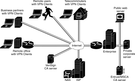
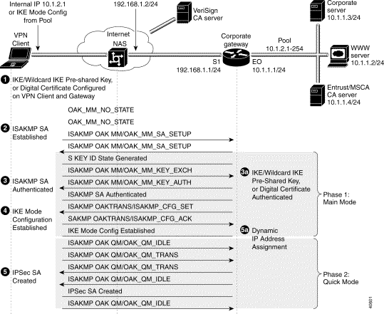
Figure 2-3 shows the protocol negotiation sequence between one VPN Client and a gateway. Table 2-1 describes the events displayed in this protocol negotiation sequence.
|
Note Although you may not have all encryption features configured for your VPN, Figure 2-3 shows the period during IKE negotiation during which each feature performs its task. |
| Event | Description of Cisco Secure VPN Client | Description of NAS and Gateway | ||
|---|---|---|---|---|
1. | To configure VPN access for remote corporate employees, the gateway administrator performs the following tasks:
Result: A method of assigning internal corporate IP addresses is assigned to each VPN Client. | To configure VPN access for remote corporate employees, the gateway administrator ensures the static IP address configured on the VPN Client is within the IP range of the corporate subnet. The gateway administrator also performs the following tasks:
Result: A method of assigning internal corporate IP addresses is assigned to each VPN Client. | ||
2. | To start IKE negotiations, the VPN Client sends attributes including KE (Diffie-Hellman keys) and NON (non-repudiation) to the gateway during the first part of ISAKMP OAK MM state.
Result: ISAKMP SA is created. | To start IKE negotiations, the VPN Client establishes ISAKMP SA with the gateway in the OAK_MM_SA_SETUP state. Setting up ISAKMP SA is the first part of Phase 1, Main Mode in IKE negotiation. Result: ISAKMP SA is created. | ||
3. | To authenticate ISAKMP SA, the VPN Client sends attributes including predefined attributes and a CERT_REQ (certificate request) and VID (vendor identification of the certificate authority) to the gateway during the second part of ISAKMP OAK MM state. Result: ISAKMP SA is authenticated. | To authenticate ISAKMP SA, the VPN Client and the gateway participate in a Diffie-Hellman key exchange, OAK_MM_KEY_EXCH, to exchange public keys. Using either digital certificates or pre-shared keys, the gateway authenticates the VPN Client during the OAK_MM_KEY_AUTH state. Authentication of ISAKMP SA is the second part of Phase 1, Main Mode in IKE negotiation. Result: ISAKMP SA is authenticated. | ||
4. | To get a dynamically-assigned IP address from the enterprise, the VPN Client receives the dynamic IP address from the pool of IP addresses on the gateway during the ISAKMP OAK TRANS state, which occurs during the ISAKMP OAK QM state. Result: IKE Mode Configuration occurs. | To get a dynamically-assigned IP address from the enterprise, the gateway transparently assigns the VPN Client a dynamic IP address from a pool of IP addresses during the ISAKMP_CFG_SET state. Then, the gateway receives an acknowledgement of having received the IP address from the VPN Client during the ISAKMP_CFG_ACK state. Result: IKE Mode Configuration occurs. | ||
5. | To finish IKE negotiations, the VPN Client loads the IPSec SA from the gateway during the ISAKMP OAK QM state. Result: IPSec SA is established. | To finish IKE negotiations, the VPN Client establishes the idle Quick Mode state (OAK_QM_IDLE) with the gateway. The VPN Client's internal attributes define the IPSec SA to be transmitted to the gateway during the OAK_QM_TRANS state. The IPSec SA from the VPN Client is authenticated with the gateway and may be used for subsequent Quick Mode exchanges. Result: IPSec SA is established. |
| Clients (Remote Access) | Gateway (Enterprise) | |||
|---|---|---|---|---|
| Chassis Type | One of the following computers, with Pentium processor or equivalent:
| For hardware information on interoperable networking devices, see the following:
| ||
| Hardware | For required hardware on the computer, see the "Cisco Secure VPN Client Documentation" section in the "Preface" of this guide.
| |||
| Software | One of the following clients:
For supported operating systems, see the "Cisco Secure VPN Client Documentation" section in the "Preface" of this guide. This information is available in the "System Requirements" section of the VPN Client release notes. | An IPSec software image from a supported Cisco IOS release. For supported Cisco IOS releases, see the related release notes in "Cisco Secure VPN Client Documentation" section in the "Preface" of this guide. This information is available in the "Network Requirements" section of the VPN Client release notes. | ||
| Memory | For memory requirements, see the "Cisco Secure VPN Client Documentation" section in the "Preface" of this guide. This information is available in the "System Requirements" section of the VPN Client release notes. | For memory on hardware devices, see "Platform-Specific Documents" section in the "Preface" of this guide. This information is usually available in the "Overview" chapter of the hardware installation guide for your hardware networking device. | ||
Ethernet IP Address
| Internal IP Address on VPN Client or Pre-shared Secret: cisco1234 | Outside S/1 interface: Inside E/0 interface: Corporate Subnet: Pre-shared secret: cisco1234 | ||
| Protocol | Native Microsoft TCP/IP, IPSec Security Protocol | IPSec Security Protocol |
![]()
![]()
![]()
![]()
![]()
![]()
![]()
![]()
Posted: Fri Aug 18 07:33:04 PDT 2000
Copyright 1989-2000©Cisco Systems Inc.