cc/td/doc/product/dsl_prod/c600s/c626
hometocprevnextglossaryfeedbacksearchhelp
PDF

Table of Contents

Installation Procedures

Installation Procedures

This chapter provides information about installing your Cisco 626. If you are not familiar with the hardware or software parameters presented here, please consult your Service Provider (SP) for the values needed.

2.1 Checklist for Installing the Cisco 626

The following table lists the tasks to be completed when installing the Cisco 626.


Table 2-1: Checklist for Installation

Installation Procedures Page Number

Unpack and Inspect Contents of the Shipping Carton

2-1

Set Up the Cisco 626 Hardware Environment :

2-3

2-3

2-4

2-5

2.2 Unpack and Inspect Contents of the Shipping Carton

Open the shipping carton carefully and check that the contents include the items you ordered. You can identify the Cisco 626 by the product name on the bottom of the front end of the modem (the end with the LEDs).

The contents of your carton may vary depending on your equipment provider. The following graphic shows the minimum contents for all the Cisco 626 shipments. The following table shows a list of the standard 626 shipment contents.


Table 2-2:
List of Standard Contents in Shipment

Contents Description

Cisco 626

Cisco's ADSL Modem for home/office use

Cisco 626 ATM ADSL User's Guide

Technical documentation for the Cisco 626

Power Supply

AC power adapter

ADSL cable

RJ-11 phone cable (14 ft)

ATM25 cable

Category 5 cable (6 ft)

Your shipment may also contain a management cable.


Figure 2-1:
RJ45-to-DB9 Serial Port Management Cable


Note Contact Cisco or your equipment provider if any items you ordered were not delivered. Refer to
"System Connectors" for information on connector pin assignments.

2.3 Hardware Requirements

The following hardware is necessary to configure management virtual connections:


Note If only a DB25 serial port is available on the computer, a
DB9-to-DB25 adapter is also needed to connect the RJ45 cable to the computer.

2.4 Set Up the Cisco 626 Hardware Environment

Consult the following section to set up the hardware environment for your Cisco 626.

2.4.1 Connect the Management Port to the Serial Port

Perfrom the following procedure to connect the Cisco 626 for configuration of management VCs and/or passwords.

Step 1 Connect the RJ45 connector on the serial cable to the 626 management port. See Figure 2-2 for location of the management port.

Step 2 Connect the other end of the serial cable to the computer serial port. If your computer only uses a DB25 serial port, a DB9-to-DB25 adapter is needed in order to connect the RJ45 cable.

Step 3 Use a terminal access program to access the Cisco 626.

Step 4 Login to the CBOS as outlined in the "Logon to the CBOS" section on page 3-2.
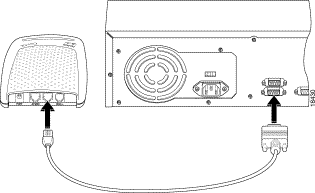

Figure 2-2: Management Port Cabling


2.4.2 Configure the Serial Port

Use a terminal access program (such as Hyperterminal in Windows) to set the COM protocol to the settings listed below.
2.4.3 Connect All Cables to the Network Using a POTS Splitter

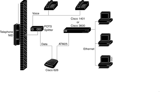
A POTS splitter separates data signals from voice signals on your phone line. The POTS splitter works by running a separate data line from the voice line, so that the ADSL modem has a dedicated cable for data transmission. Figure 2-3 shows phone equipment connected to a POTS splitter.


Figure 2-3:
Phone Equipment Connected Through a POTS Splitter


Note The POTS splitter can also be installed on the outside of the house adjacent to the telephone network interface device (NID).

Perform the procedure below to install the Cisco 626 using a POTS splitter.

Step 1 Plug the Power Connector into the back of the unit.

Step 2 Connect the ATM25 cable into the ATM25 connector on the rear panel of the Cisco 626. Connect the other end of the ATM25 cable to your premise router; for example a Cisco 1401.

Step 3 Connect the RJ11 cable to the WALL connector on the rear panel of the 626. Connect the other end of that cable to the POTS Splitter.

The following figure illustrates how to
connect all cables to the rear panel .
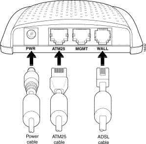

Figure 2-4:
Rear Panel Cabling


hometocprevnextglossaryfeedbacksearchhelp
Posted: Tue Mar 16 08:34:15 PST 1999
Copyright 1989-1999©Cisco Systems Inc.