|
|

The following illustration shows the connectors located on the rear panel of the Cisco 626 unit.

The following ports are located on the backside of the Cisco 626.
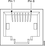
The LAN interface uses an RJ-45 connector that conforms to the ATM Forum Specification for ATM 25.6Mbits over a category 3 (10Mbps) or category 5 (100Mbps) twisted-pair wire at a distance of up to 100 meters or less. The following table shows the connector pinouts.
| Pin | Signal |
|---|---|
7 | TXD+ |
8 | TXD- |
1 | RXD+ |
2 | RXD- |

The management port uses an RJ-45 connector.
The connector pinouts for the management port are shown in the following table.
| Pin | Signal |
|---|---|
4 | Ground |
5 | RX |
6 | TX |

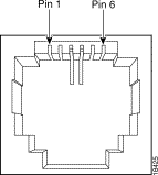
The Asymmetric Digital Subscriber Line (ADSL) port uses an RJ-11 connector. The following table shows the connector pinouts for the ADSL connector. The sections that follow illustrate the ADSL connector. The ADSL connector is labelled as "WALL" on the Cisco 626 rear panel.
| Pin | Signal |
|---|---|
3 | Ring |
4 | Tip |

![]()
![]()
![]()
![]()
![]()
![]()
![]()
![]()
Posted: Tue Mar 16 08:31:23 PST 1999
Copyright 1989-1999©Cisco Systems Inc.