|
|

This chapter describes the DPTIP and contains the following sections:
The DPT Interface Processor (DPTIP) is a dual-width OC-12c interface processor based on VIP2 technology that provides shared IP over SONET capability in Cisco 7500 series routers. (See Figure 1-1.) The DPTIP is available in four models:
The DPTIP provides Cisco 7500 series routers with two SC duplex ports. Each SC duplex port provides the physical connection to an adjacent device in a DPT ring.
The DPTIP is designed to be deployed in SONET OC-12 DPT rings. DPT rings can also be connected to SONET Add Drop Multiplexers (ADMs), thus allowing for the creation of small, or very large DPT rings.

The DPTIP supports the following functions:
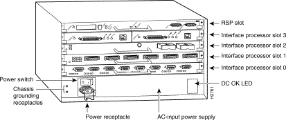
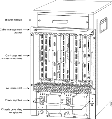
The DPTIP is oriented horizontally in the Cisco 7505 and vertically in the Cisco 7507 and Cisco 7513.
The following terms and acronyms are used in this publication:
Spatial Reuse Protocol (SRP) is a media-independent MAC layer protocol that operates over two counterrotating fiber-optic rings. The dual rings provide survivability of data in case of a failed node or a break in connecting cables by rerouting the data path over the alternate ring. SRP provides a more efficient use of bandwidth by having packets traverse only the part of the ring necessary to get to the destination node. Once the packet has reached the destination node, it is removed from the ring, allowing other parts of the ring to reuse the bandwidth. Data packets travel on one ring, while associated control packets travel in the opposite direction on the alternate ring, ensuring that the data takes the shortest path to its destination. (See Figure 1-2.)
Each node on a DPT ring represents a Cisco 7200 series router, Cisco uBR7246, Cisco 7200 VXR router, Cisco 7500 series router, or a Cisco 12000 series Gigabit Switch Router (GSR). A Cisco 7200 series, Cisco uBR7246, Cisco 7200 VXR, or Cisco 7500 series router can be used as an aggregation device for the Cisco 12000 series GSR. The Cisco 7200 series, Cisco uBbr7246, Cisco 7200 VXR, or Cisco 7500 series router collects data from lower-speed interfaces and passes it to the Cisco 12000 series GSR. Typically, more Cisco 7200 series, Cisco uBR7246, Cisco 7200 VXR, or Cisco 7500 series routers aggregate traffic toward fewer Cisco 12000 GSRs.
A DPT ring can contain up to 64 nodes at one time, with each node holding a map of the ring topology that it continually updates to ensure that data takes the shortest path to its destination. The frequency of the updating can be manually configured. See the "Configuring the DPT Topology Feature" section.
The DPT interface uses the SONET ring architecture, which provides redundancy and protection from a failed node or fiber cut through the use of the Intelligent Protection Switch (IPS). When the DPT ring topology changes because of a node failure, as shown in Figure 1-3, the system software automatically puts the node into pass-through mode, where data continues to pass through the node, but the node is no longer seen on the ring topology map. In the event of a fiber cut, ring wraps are created to redirect data traffic over the alternate ring. (See Figure 1-4.)
In both pass-through mode and wrap mode, data packets not destined for the affected node still reach their destination.
The SONET specification for fiber-optic transmission defines two types of fiber: single-mode and multimode. Signals travel farther through single-mode fiber than through multimode fiber.
The maximum distance for single-mode installations is determined by the amount of light loss in the fiber path. Good-quality single-mode fiber with very few splices can carry an OC-12c/STM-4 signal 50 miles (80 kilometers) or more. Good-quality multimode fiber can carry the signal up to 1640 feet (500 meters). If your environment requires the signal to travel close to the typical maximum distance (as listed in Table 1-1), use an optical time-domain reflectometer (OTDR) to measure the power loss.
| Cable | Power Budget | Transmit Power | Receive Power | Typical Maximum Distance |
|---|---|---|---|---|
Single-mode intermediate range | 12 dB | -28 to -8 dBm | 9.3 miles (15 km) | |
Single-mode long range | 25 dB | -3 to 2 dBm at | -28 to -8 dBm | 24.8 miles (40 km) |
Single-mode extended reach | 25 dB | -2 to 3 dBm at 1550 nm | -28 to -7 dBm | 50 miles (80 km) |
Multimode | 6 dB | -20 to -14 dBm at 1270 to 1380 nm | -26 to -14 dBm | 1640.4 feet (500 m) |
| 1dBm = decibels per milliwatt 2nm = nanometer |
The eight LEDs on the faceplate of the DPTIP (see Figure 1-5), show the DPTIP status, as well as the status of the individual ports. Table 1-2 explains the DPTIP LED indications.

| LED Label | Color | State | Function |
ENABLED | Green | On | Indicates that the DPTIP is enabled for operation; however, the interface port might be in the shutdown state. |
PASS-THROUGH | Amber | On | Indicates the DPTIP is in a pass-through state. |
RX PKTS | Green | On | Indicates the DPTIP has received a packet. This LED flickers in normal operation, indicating traffic. |
RX CARRIER | Green | On | Indicates the DPTIP has detected valid SONET or SDH framing on the received carrier. |
ACTIVE | Green | On | Indicates that side A or B of the DPTIP is functioning. |
Use a single-mode or multimode fiber-optic interface cable to connect your Cisco 7500 series router to another router or switch. In general, multimode cables are gray or orange, and single-mode cables are yellow.
 |
Note Single-mode and multimode fiber-optic cables are not available from Cisco Systems. |
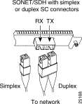
For SONET or SDH single-mode and multimode fiber-optic connections, use one duplex SC-type connector (see Figure 1-6) or two simplex SC-type connectors. (See Figure 1-7.)


Attach either one duplex fiber-optic cable or two simplex fiber-optic cables between the DPTIP and the device to which the DPTIP is connected. Observe the receive (RX) and transmit (TX) cable relationship shown in Figure 1-8.

The following warnings apply when you work with fiber-optic cable ports.
 |
Warning Because invisible radiation may be emitted from the aperture of the port when no fiber cable is connected, avoid exposure to radiation and do not stare into open apertures. |
 |
Warning Class 1 laser product (single-mode). |
 |
Warning Class 1 LED product (multimode). |
This section describes the interface processor slot numbering for the Cisco 7500 series routers. Figure 1-9, Figure 1-10, and Figure 1-11 show the processor slot locations and numbering for the Cisco 7505, Cisco 7507, and Cisco 7513 routers.


This section describes how to identify the interface address for the DPTIP in Cisco 7500 series routers. Interface addresses specify the actual physical location of each interface on a router or switch.
The interface address is composed of a three-part number in the format interface-processor-slot- number/port-adapter-slot-number/interface-port-number. See Table 1-3 for the interface address format. The DPTIP is a dual-width interface processor with one interface; therefore, the port adapter slot number and the interface port number are always 0.
For a DPTIP in interface processor slot 3 of a Cisco 7500 series router, the interface address of the DPTIP interface is 3/0/0 (interface processor slot 3, port adapter slot 0, and interface 0). If you remove the DPTIP from interface processor slot 3 and install it in interface processor slot 2, the interface address becomes 2/0/0.
| Platform | Interface Address Format | Numbers | Syntax |
|---|---|---|---|
DPTIP in Cisco 7500 series routers | Interface-processor-slot-number/ | Interface processor slot—0 through 12 (depends on the number of slots in the router) Port adapter slot—always 0 for the DPTIP Interface port—always 0 for the DPTIP | 3/0/0
|
 |
Note Although the processor slots in the 7-slot Cisco 7507 and the 13-slot Cisco 7513 and Cisco 7576 are vertically oriented and those in the 5-slot Cisco 7505 are horizontally oriented, all Cisco 7500 series routers use the same method for slot and port numbering. |
![]()
![]()
![]()
![]()
![]()
![]()
![]()
![]()
Posted: Fri Feb 2 19:29:13 PST 2001
All contents are Copyright © 1992--2001 Cisco Systems, Inc. All rights reserved.
Important Notices and Privacy Statement.