|
|

Table Of Contents
Using the EXEC Command Interpreter
Configuring the DPTIP Interface
Performing a Basic Configuration
Configuring the Intelligent Protection Switch Feature
Configuring the DPT Topology Feature
Changing the Default Values of Configuration Parameters
Using show Commands to Check System Status
Adding or Removing Nodes in a DPT Ring
Removing a Node from a DPT Ring
Using show Commands to Verify the New Interface Status
Using the ping Command to Verify Network Connectivity
Configuring the DPTIP
To continue your DPTIP installation, you must configure the DPTIP interface.
This chapter contains the following sections:
•
Using the EXEC Command Interpreter
•
Using the EXEC Command Interpreter
You modify the configuration of your router through the software command interpreter called the EXEC (also called enable mode). You must enter the privileged level of the EXEC command interpreter with the enable command before you can use the configure command to configure a new interface or change the existing configuration of an interface. The system prompts you for a password if one has been set.
The system prompt for the privileged level ends with a pound sign (#) instead of an angle bracket (>). At the console terminal, use the following procedure to enter the privileged level:
Step 1
Router> enable
Password:
Step 2
When you enter the correct password, the system displays the privileged-level system prompt (#):
Router#To configure the new interface, proceed to the "Configuring the DPTIP Interface" section.
Configuring the DPTIP Interface
After you verify that the new DPTIP is installed correctly (the enabled LED goes on), use the privileged-level configure command to configure the new interface. Have the following information available:
•
•
If you installed a new DPTIP or if you want to change the configuration of the existing interface, you must enter configuration mode to configure the new interface. If you replaced a DPTIP that was previously configured, the system recognizes the new interfaces and brings each of them up in their existing configuration.
For a summary of the configuration options available and instructions for configuring a DPTIP, refer to the appropriate configuration publications listed in the "Related Documentation" section on page vi.
You execute configuration commands from the privileged level of the EXEC command interpreter, which usually requires password access. Contact your system administrator, if necessary, to obtain password access. (See the "Using the EXEC Command Interpreter" section for an explanation of the privileged level of the EXEC.)
This section contains the following subsections:
•
•
•
Shutting Down the Interface
Before you remove an interface that you will not replace, use the shutdown command to shut down (disable) the interface to prevent anomalies when you reinstall the new or reconfigured interface. When you shut down an interface, it is designated administratively down in the show command displays.
Follow these steps to shut down an interface:
Step 1
Step 2
Router# configure terminalEnter configuration commands, one per line. End with CNTL/Z.Router(config)#Step 3
Note
When you have finished, press Ctrl-Z—hold down the Control key while you press Z—or enter end or exit to exit configuration mode and return to the EXEC command interpreter.
Step 4
Router# copy running-config startup-config[OK]Router#The system displays an OK message when the configuration has been stored in NVRAM.
Step 5
show interfaces command (followed by the interface type and interface address of the interface) to display the specific interface. Table 4-2 provides examples.
Step 6
a.
b.
Use the copy running-config startup-config command.c.
show interfaces command followed by the interface type and interface address of the interface.For complete descriptions of software configuration commands, refer to the publications listed in the "Related Documentation" section on page vi.
Performing a Basic Configuration
This section describes guidelines for performing a basic configuration: enabling the DPT port adapter and specifying IP routing. You might also need to enter other configuration subcommands, depending on the requirements for your system configuration and the protocols you plan to route on the interface. After configuring the DPTIP in a Cisco 7500 series router, see the "Adding a Node to a DPT Ring" section for adding the router to a DPT ring.
Before using the configure command, you must enter the privileged level of the EXEC command interpreter with the enable command. The system prompts you for a password if one has been set.
Use the following procedure to configure the DPTIP. Press the Return key after each configuration step, unless otherwise noted.
Step 1
Router# show running-configFor an example of output from the show running-config command, see the "Using show Commands to Check System Status" section.
Step 2
Router# configure terminalStep 3
Router(config)# ip routingStep 4
Router(config)# interface srp 1/0/0
Note
Step 5
Router(config)# interface srp 1/0/0Router(config-if)# ip address 10.1.2.3 255.0.0.0Step 6
Router(config)# interface srp 1/0/0Router(config-if)# srp framing sonet side bStep 7
Router(config)# interface srp 1/0/0Router(config-if)# srp clock-source internal side aStep 8
Router(config)# interface srp 1/0/0Router(config-if)# no shutdownThe no shutdown command passes an enable command to the DPTIP. It also causes the DPTIP to configure itself based on the previous configuration commands that were sent.
Step 9
Step 10
Step 11
Router# copy running-config startup-configThe system displays an OK message when the configuration has been stored.
After you have completed your configuration, you can check it using show commands. For an explanation of show commands, see the "Using show Commands to Check System Status" section.
Configuring the Intelligent Protection Switch Feature
Intelligent Protection Switch (IPS) ensures that ring traffic flow continues uninterrupted even if device or ring failures occur. IPS protects the DPT ring by initiating ring wraps that route traffic in the opposite direction over the alternate ring. The system software creates ring wraps by issuing an IPS request when failures are detected. The five types of IPS requests are hierarchical, with higher-priority requests taking precedence over lower-priority requests. For example, if a signal failure was detected at the same time that an operator entered a manual switch request, the system would create the ring wrap at the point of signal failure and the manual switch would be ignored. Table 4-3 lists the types of IPS requests in order of priority.
Table 4-3 IPS Request Hierarchy
1 Forced switch
Operator
2 Signal fail
Software
3 Signal degrade
Software
4 Manual switch
Operator
5 Wait to restore
Software
When you add a node to a DPT ring, you must create a break in the ring. You can create the break by initiating a forced switch request using the srp ips request command. See the "Adding a Node to a DPT Ring" section. The following example shows a forced switch request on side A of the DPTIP:
Router(config)# interface srp 2/0/0Router(config-if)# srp ips request fs side AIf you need more detailed information about IPS commands, refer to publications listed in the
"Related Documentation" section on page vi.Configuring the DPT Topology Feature
Every node on a DPT ring maintains a topology map of the ring so that it knows where to route traffic. It updates the topology map by periodically sending a query, called a topology discovery packet, out onto the ring. Each node on the ring adds its own MAC address to the packet. When the discovery packet returns to the originating node, the contents of the packet are used to update the node topology map. You use the srp topology-timer command to set the frequency with which the node sends out topology discovery packets.
The show srp topology command is used to display the MAC addresses of each node on a DPT ring. See the "Using show Commands to Check System Status" section.
If you need more detailed information about DPT topology commands, see the "Related Documentation" section on page vi.
Changing the Default Values of Configuration Parameters
The default values of the DPTIP configuration parameters can be changed to match your network requirements. Table 4-4 lists the configuration parameter, the command used to alter it, and the default value of the parameter. If you need more detailed configuration information, refer to the publications listed in the "Related Documentation" section on page vi.
Using show Commands to Check System Status
The system maintains different kinds of information about its configuration and system status. This information can be accessed by using the show commands. This section contains show command information relevant to the installation and configuration of the DPTIP. See the "Related Documentation" section on page vi to locate more detailed information on show commands.
This section contains examples of the following commands:
•
•
•
•
•
•
•
•
•
Use the show running-config command to display the currently running configuration. The example below shows that the current software version is Cisco IOS Release 12.0(6)S, a DPTIP is installed (the DPTIP is shown as interface SRP1/0/0), and the IP address of the DPTIP is 192.168.0.20 255.255.255.0:
Router# show running-configBuilding configuration...Current configuration:version 12.0(6)Sservice timestamps debug uptimeservice timestamps log datetimeno service password-encryptionservice udp-small-serversservice tcp-small-servers!hostname uut2!ip subnet-zeroip host abrick 192.168.254.254ip host curly 192.168.1.20ip host sink 192.168.1.30ip host sneha 192.168.1.40ip name-server 192.168.2.132!!!interface SRP1/0/0mac-address 0010.5555.6666ip address 192.168.0.20 255.255.255.0no ip directed-broadcastno ip route-cache cefno ip route-cache distributedno keepaliveno srp random-detect input highno srp random-detect input mediumno srp random-detect input lowUse the show version command to display the configuration of the system hardware, and Cisco IOS software information. The following example shows that the Cisco IOS version is 12.0(6)S, and the DPTIP is shown as 1 VIP2 R5K controller (1 SRP):
Router# show versionCisco Internetwork Operating System SoftwareIOS (tm) RSP Software (RSP-JV-M), Version 12.0(19981112:225526) [iks-srppa 236]Copyright (c) 1986-1998 by cisco Systems, Inc.Compiled Fri 04-Dec-98 12:59 by iksImage text-base:0x600108F8, data-base:0x60E72000ROM:System Bootstrap, Version 12.0(6)S(2) [nitin 2], RELEASE SOFTWARE (fc1)BOOTFLASH:GS Software (RSP-BOOT-M), Version 11.1(8)CA,router uptime is 2 days, 21 hours, 7 minutesSystem restarted by reloadSystem image file is "tftp://223.255.254.254/muck/karthiks/rsp-jv-mz"cisco RSP2 (R4700) processor with 65536K/2072K bytes of memory.R4700 processor, Implementation 33, Revision 1.0Last reset from power-onG.703/E1 software, Version 1.0.G.703/JT2 software, Version 1.0.X.25 software, Version 3.0.0.SuperLAT software (copyright 1990 by Meridian Technology Corp).Bridging software.TN3270 Emulation software.1 EIP controller (4 Ethernet).1 VIP2 R5K controller (1 SRP).4 Ethernet/IEEE 802.3 interface(s)123K bytes of non-volatile configuration memory.20480K bytes of Flash PCMCIA card at slot 0 (Sector size 128K).8192K bytes of Flash internal SIMM (Sector size 256K).No slave installed in slot 7.Configuration register is 0x0WARNING:Chassis Interface not presentUse the show protocols command to show whether a DPTIP is up, as shown in the following example:
router# show protocolsGlobal values:Internet Protocol routing is enabledEthernet0/0/0 is up, line protocol is upInternet address is 192.168.6.2/16Ethernet0/0/1 is administratively down, line protocol is downInternet address is 192.168.0.1/8Ethernet0/0/2 is up, line protocol is downEthernet0/0/3 is administratively down, line protocol is downSRP2/0/0 is up, line protocol is upInternet address is 192.168.0.40/8Use the show diag command to view system hardware information. The following example shows a DPTIP installed in slot 0:
Router# show diag 0Slot 0:Physical slot 0, ~physical slot 0xF, logical slot 0, CBus 0Microcode Status 0x4Master Enable, LED, WC LoadedBoard is analyzedPending I/O Status:NoneEEPROM format version 1VIP2 R5K controller, HW rev 2.01, board revision B0Serial number:06741587 Part number:73-2167-03Test history:0x0 RMA number:00-00-00Flags:cisco 7000 board; 7500 compatibleEEPROM contents (hex):0x20:01 1E 02 01 00 66 DE 53 49 08 77 03 00 00 00 000x30:58 00 00 00 00 00 00 00 00 00 00 00 00 00 00 00Slot database information:Flags:0x4 Insertion time:0x15FC (2d21h ago)Controller Memory Size:32 MBytes DRAM,4096 KBytes SRAMPA Bay 0 Information:SRP PA,1 port,PA-SRP-MMEEPROM format version 1HW rev 1.00, Board revision UNKNOWNSerial number:00000000 Part number:73-3250-01
Note
Use the show controllers srp command to display the location of the DPTIP and other configuration information specific to the DPTIP, as shown in the following example:
Router# show controllers srpSRP2/0/0SRP2/0/0 - Side A (Outer RX, Inner TX)SECTIONLOF = 2 LOS = 0 BIP(B1) = 140Active Alarms:NoneLINEAIS = 0 RDI = 2 FEBE = 506 BIP(B2) = 1425Active Alarms:NonePATHAIS = 0 RDI = 0 FEBE = 81 BIP(B3) = 68LOP = 2 NEWPTR = 0 PSE = 0 NSE = 0Active Alarms:NoneipsCOAPS = 4 PSBF = 2State:PSBF_state = FalseRx(K1/K2):00/00 Tx(K1/K2):00/00S1S0 = 00, C2 = 12CLOCK RECOVERYRDOOL = 0State:RDOOL_state = FalsePATH TRACE BUFFER :STABLERemote hostname :flipRemote interface:SRP2/0Remote IP addr :10.0.0.3Remote Ring id :OuterSRP2/0/0 - Side B (Inner RX, Outer TX)SECTIONLOF = 2 LOS = 2 BIP(B1) = 69Active Alarms:NoneLINEAIS = 0 RDI = 4 FEBE = 640 BIP(B2) = 689Active Alarms:NonePATHAIS = 0 RDI = 0 FEBE = 86 BIP(B3) = 78LOP = 0 NEWPTR = 0 PSE = 0 NSE = 0Active Alarms:NoneipsCOAPS = 12 PSBF = 0State:PSBF_state = FalseRx(K1/K2):00/00 Tx(K1/K2):00/00S1S0 = 00, C2 = 12CLOCK RECOVERYRDOOL = 0State:RDOOL_state = FalsePATH TRACE BUFFER :STABLERemote hostname :flopRemote interface:SRP2/0Remote IP addr :192.168.0.2Remote Ring id :Inner
Note
Use the show interfaces srp command to show statistics for the DPTIP interfaces, as shown in the following example:
Router# show interfaces srp 2/0/0SRP2/0/0 is up, line protocol is upHardware is SRP over SONET, address is 0000.0000.0001 (bia 0010.f60e.87ff)Internet address is 192.168.0.1/8MTU 9000 bytes, BW 625000 Kbit, DLY 100 usec, rely 255/255, load 1/255Encapsulation SRP, loopback not setLast input 00:00:23, output 00:00:03, output hang neverLast clearing of "show interface" counters 00:18:35Queueing strategy:fifoOutput queue 0/40, 0 drops; input queue 0/75, 0 drops5 minute input rate 0 bits/sec, 0 packets/sec5 minute output rate 0 bits/sec, 0 packets/sec22 packets input, 2064 bytes, 0 no bufferReceived 0 broadcasts, 0 runts, 0 giants, 0 throttles621 input errors, 621 CRC, 0 frame, 0 overrun, 0 ignored, 0 abort64 packets output, 6452 bytes, 0 underruns0 output errors, 0 collisions, 0 interface resets0 output buffer failures, 0 output buffers swapped outUse the show srp ips command to show IPS information for a specific interface. The following example shows the MAC addresses of the two nodes that are connected to the interface, and information about the state of the connections:
router# show srp ips 2/0/0IPS Information for Interface SRP2/0/0MAC AddressesSide A (Outer ring RX) neighbour 0000.0000.0002Side B (Inner ring RX) neighbour 0000.0000.0001Node MAC address 0000.0000.0003IPS StateSide A not wrappedSide B wrappedSide A (Inner ring TX) IPS pkt. sent every 10 sec. (next pkt. after 6 sec.)Side B (Outer ring TX) IPS pkt. sent every 10 sec. (next pkt. after 6 sec.)IPS WTR period is 60 sec. (timer is inactive)Node IPS State WRAPPEDIPS Self Detected RequestsSide A IDLESide B SFIPS messages receivedSide A (Outer ring RX) {0000.0000.0002,SF ,L,1024}Side B (Inner ring RX) {0000.0000.0001,IDLE,S,1024}IPS messages transmittedSide A (Inner ring TX) {0000.0000.0003,SF ,L,1024}Side B (Outer ring TX) {0000.0000.0003,SF ,S,1024}Topology pkt. sent every 20 sec. (next pkt. after 1 sec.)Last received topology pkt. 00:00:18Nodes on the ring:2Hops (outer ring) Address0 0000.0000.0003 Wrapped1 0000.0000.0002 WrappedUse the show srp topology command to show the identity of the nodes on the DPT ring according to their MAC addresses. The following examples show a three-node DPT ring. In the second example, nodes 1 and 3 are wrapped:
Router# show srp topologyTopology Map for Interface SRP2/0/0Topology pkt. sent every 61 sec. (next pkt. after 16 sec.)Last received topology pkt. 00:00:45Nodes on the ring:3Hops (outer ring) Address0 0000.0000.00011 0000.0000.00022 0000.0000.0003Router# show srp topologyTopology Map for Interface SRP2/0/0Topology pkt. sent every 61 sec. (next pkt. after 54 sec.)Last received topology pkt. 00:00:07Nodes on the ring:3Hops (Outer ring) Address0 0000.0000.0001 Wrapped1 0000.0000.00022 0000.0000.0003 WrappedUse the show srp source-counters command to show the number of packets received or rejected when SRP count and reject have been configured. The following example shows 1201 packets have come from another node, and none have been rejected:
Router# show srp source-countersSource Address Information for Interface SRP2/0/0000a.1234.5678, pkt. count 1201000b.1234.5678, rejectCreating a DPT Ring
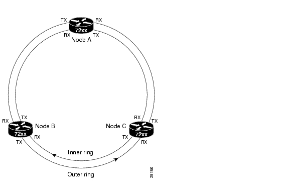
A DPT ring may contain as many as 32 nodes, or as few as 2 nodes. This section documents the layout and configuration of a three-node DPT ring. It is assumed that the actual physical installation of the Cisco 7500 series routers has already been accomplished.
Before the DPT ring can be created, each Cisco 7500 series router (node) must have a DPTIP installed and configured. See Chapter 3, "Removing and Installing Interface Processors," and the "Configuring the DPTIP Interface" section. Once the individual nodes are configured, the inner and outer rings of the DPT ring must be connected as shown in Figure 4-1, and the DPTIPs must be enabled. The procedure below describes the internodal connections of the DPT ring and the configuration commands used to create the ring.
Figure 4-1 Three-Node DPT Ring
Step 1
Router(config)# interface srp 1/0/0Router(config-if)# shutdownStep 2
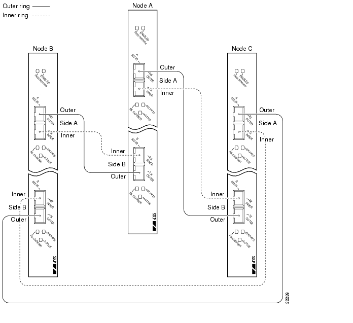
Note
Figure 4-2 Internodal Connections of a Three-Node DPT Ring
Step 3
Router(config)# interface srp 1/0/0Router(config-if)# no shutdownStep 4
Adding or Removing Nodes in a DPT Ring
The following sections describe the procedures for adding or removing a node in a DPT ring:
•
Adding a Node to a DPT Ring
When a new node is to be installed in a DPT ring, a DPTIP is first installed and configured in the Cisco 7500 series router, and the router is then installed and configured as a node in the DPT ring. This section describes the procedure for adding a node to a DPT ring.
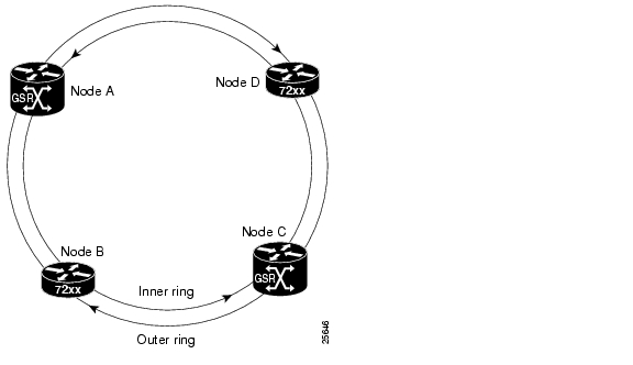
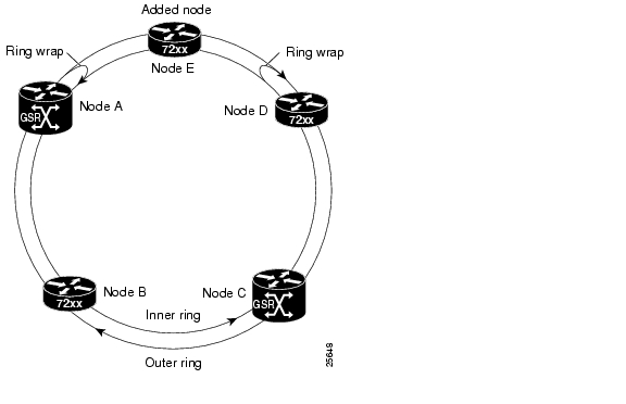
To add a node to a DPT ring, you must first reroute the traffic flow over the ring through an alternate path, by creating a ring wrap where the new node is to be installed. Figure 4-3 shows a four-node DPT ring. Use the following procedure to add a node between nodes A and D on the ring:
Step 1
Figure 4-3 DPT Ring Topology with Four Nodes
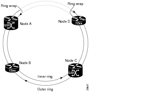
Figure 4-4 DPT Ring with Ring Wraps Created by a Forced Switch
Step 2
Step 3
Step 4
Note
Step 5
Step 6
Step 7
Step 8
Step 9
Figure 4-5 DPT Ring Topology with an Added Node
Note
Removing a Node from a DPT Ring
This section describes the procedure for removing a node from a DPT ring. The following steps describe how to remove node D from a four-node DPT ring, similar to that shown in Figure 4-3.
Step 1
Step 2
Step 3
Step 4
Step 5
Step 6
This completes the procedure for removing a node from a DPT ring.
Checking the Configuration
After configuring the new interface, use the show commands to display the status of the new interface or all interfaces, and use the ping and loopback commands to check connectivity. This section includes the following subsections:
•
•
Using show Commands to Verify the New Interface Status
Table 4-6 demonstrates how you can use the show commands to verify that new interfaces are configured and operating correctly and that the DPTIP appears in them correctly. Sample displays of the output of selected show commands appear in the sections that follow. For complete command descriptions and examples, refer to the publications listed in the "Related Documentation" section on page vi.
Note
Using the ping Command to Verify Network Connectivity
Using the ping command, you can verify that an interface port is functioning properly. This section provides a brief description of this command. Refer to the publications listed in the "Related Documentation" section on page vi for detailed command descriptions and examples.
The ping command sends echo request packets out to a remote device at an IP address that you specify. After sending an echo request, the system waits a specified time for the remote device to reply. Each echo reply is displayed as an exclamation point (!) on the console terminal; each request that is not returned before the specified timeout is displayed as a period (.). A series of exclamation points (!!!!!) indicates a good connection; a series of periods (.....) or the messages [timed out] or [failed] indicate a bad connection.
Following is an example of a successful ping command to a remote server with the address 10.0.0.10:
Router# ping 10.0.0.10 <Return>Type escape sequence to abort.Sending 5, 100-byte ICMP Echoes to 10.0.0.10, timeout is 2 seconds:!!!!!Success rate is 100 percent (5/5), round-trip min/avg/max = 1/15/64 msRouter#If the connection fails, verify that you have the correct IP address for the destination and that the device is active (powered on), and repeat the ping command.
![]()
![]()
![]()
![]()
![]()
![]()
![]()
![]()
Posted: Wed Aug 25 16:29:58 PDT 2004
All contents are Copyright © 1992--2004 Cisco Systems, Inc. All rights reserved.
Important Notices and Privacy Statement.