|
|

This chapter describes how to remove the DPTIP from supported platforms and also how to install a new or replacement DPTIP. This chapter contains the following sections:
Each interface processor circuit board is mounted to a metal carrier and is sensitive to electrostatic discharge (ESD) damage.
 |
Note When an interface processor slot is not in use, a blank interface processor must fill the empty slot to allow the router or switch to conform to electromagnetic interference (EMI) emissions requirements and to allow proper airflow across the interface processor modules. If you plan to install a new interface processor in a slot that is not in use, you must first remove the blank interface processor. |
The function of the ejector levers on the DPTIP is to align and seat the card connectors in the backplane. Failure to use the ejector levers and insert the DPTIP properly can disrupt the order in which the pins make contact with the backplane. Follow the DPTIP installation and removal instructions carefully, and review the following examples of incorrect insertion practices and results:
Use the ejector levers when removing the DPTIP to ensure that the board connector pins disconnect from the backplane in the logical sequence expected by the system. Any DPTIP that is only partially connected to the backplane can hang the bus. Detailed steps for correctly performing OIR are included with the following procedures for installing and removing the DPTIP.
The captive installation screws on the ends of each faceplate (see Figure 3-1), when tightened, provide EMI shielding and also help ensure proper seating in the backplane. After using the ejector levers to install the DPTIP, immediately tighten the captive installation screws. These screws must be tightened to meet EMI specifications and to prevent accidentally dislodging the DPTIP from the backplane.
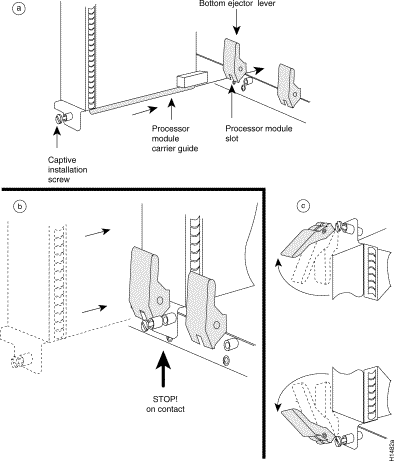
 |
Caution Always handle the interface processor by the carrier edges and handle; never touch the port adapter components or connector pins. (See Figure 3-2.) |
Several platforms support online insertion and removal (OIR) of interface processors; therefore, you do not have to power down routers when removing and replacing a DPTIP on Cisco 7500 series routers.
 |
Note As you disengage the interface processor from the router, OIR administratively shuts down all active interfaces in the interface processor. |
 |
Note Before you begin installation, read "Preparing for Installation," for a list of parts and tools required for installation. |
Observe the following warnings and cautions when installing or removing interface processors.
 |
Warning Only trained and qualified personnel should install, replace, or service this equipment. |
 |
Caution Do not slide an interface processor all the way into the slot until you have connected all required cables. Trying to do so disrupts normal operation of the system. |
 |
Caution To prevent jamming the carrier between the upper and the lower edges of the interface processor slot, and to ensure that the edge connector at the rear of the interface processor mates with the connection at the rear of the interface processor slot, make certain that the carrier is positioned correctly, as shown in the cutaway in the following illustration. |
 |
Caution To avoid erroneous failure messages, remove or insert only one DPTIP at a time. Also, after inserting or removing a DPTIP, allow at least 15 seconds before removing or inserting another DPTIP so that the system can reinitialize and note the current configuration of all interfaces. |
 |
Caution The DPTIP assembly consists of two parts: a dual-width port adapter and a motherboard (VIP2). To prevent problems with the DPTIP and the system in which the DPTIP is installed, do not attempt to separate the DPT port adapter from its motherboard. The entire DPTIP assembly is a field-replaceable unit (FRU). |
In this section, the illustration that follows gives step-by-step instructions on how to remove and install an interface processor.
 |
Note If an ejector lever or other retaining mechanism does not move to the locked position, the interface processor is not completely seated in the midplane. Carefully pull the interface processor halfway out of the slot, reinsert it, and move the ejector lever or other mechanism to the locked position. |
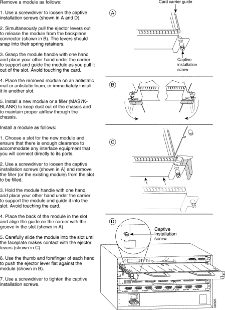 Cisco 7500 Series—Removing and Installing an Interface Processor
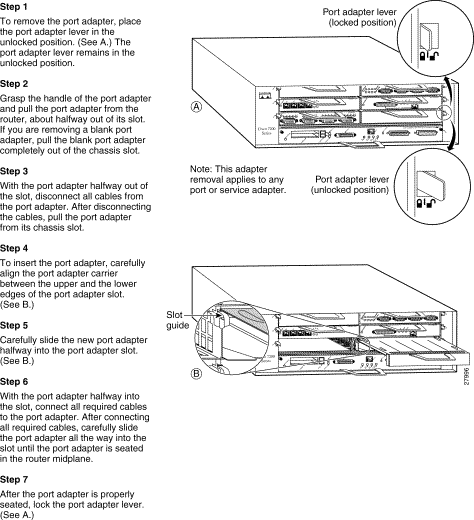
The following procedures in this section are required only if you need to replace the SDRAM DIMM.
 |
Note Use only the SDRAM DIMM from Cisco Systems. A Cisco manufacturing part number appears on the SDRAM DIMM. |
 |
Caution To prevent ESD damage, handle the DIMM by the card edges only. (See Figure 3-6.) Place a removed DIMM on an antistatic mat and store it in an antistatic container. |
Use the following procedure to remove the existing DIMM:
Step 2 Place the DPTIP on an antistatic mat or pad and ensure that you are wearing an antistatic device, such as a wrist strap. Position the DPTIP so that the handle is away from you and the bus connector is toward you—the opposite of the position shown in Figure 3-3.
Step 3 Locate the SDRAM DIMM. See Figure 3-3.
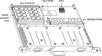
Step 4 Open the DIMM socket tabs on the DIMM to release the DIMM from the socket.
(See Figure 3-4.)
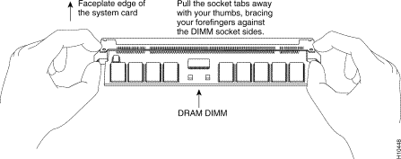
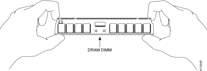
Step 5 With the DIMM socket tabs open, grasp the ends of the DIMM between your thumbs and forefingers and pull the DIMM completely out of the socket. (See Figure 3-5.) Handle the edges of the DIMM only; avoid touching the memory module, pins, and the metal traces or fingers, along the socket edge. (See Figure 3-6.)

Step 6 Place the DIMM in an antistatic container to protect it from ESD damage.
This completes the DIMM removal procedure. Proceed to the next section to install a new DIMM.
The DIMM is a sensitive component that is susceptible to ESD damage. Handle the DIMM by the edges only; avoid touching the memory modules, pins, or traces (the metal fingers along the connector edge of the DIMM). (See Figure 3-6.)
With the DPTIP in the same orientation as the previous procedure (with the handle away from you and the bus connector toward you), install the DIMM in the DIMM socket, as described in the following procedure:
Step 2 Hold the DIMM, between your thumbs and forefingers, component side up.
(See Figure 3-6.)
Step 3 Tilt the DIMM to approximately the same angle as the socket and insert the connector edge into the socket.
 |
Caution When inserting the DIMM, use firm but not excessive pressure. If you damage a socket, you will have to return the DPTIP to the factory for repair. |
Step 4 Gently push the DIMM into the socket until the socket tabs close over the ends of the DIMM. (See Figure 3-7.) If necessary, rock the DIMM gently back and forth to seat it properly.

Step 5 When the DIMM is installed, check to see that it is seated properly. If the DIMM appears misaligned, carefully remove it and reseat it in the socket. Push the DIMM firmly back into the socket until the socket tabs move into place.
This completes the DIMM replacement procedure. If required, proceed to the section "Replacing the DPTIP SRAM Daughter Card" section. Otherwise, reinstall the DPTIP in the system. (Follow the steps in the "Interface Processor Removal and Installation" section.)
Refer to the "Checking an SDRAM and SRAM Replacement" section, as required.
The following procedures in this section are required only if you need to replace the SRAM daughter card.
 |
Note Use only the SRAM daughter card from Cisco Systems. A Cisco manufacturing part number appears on the SRAM daughter card. |
 |
Caution To prevent ESD damage, handle the SRAM daughter card by the edges only. Place a removed SRAM daughter card on an antistatic mat and store it in an antistatic container. |
Use the following procedure to remove the existing SRAM daughter card:
Step 2 Place the DPTIP on an antistatic mat or pad, and ensure that you are wearing an antistatic device, such as a wrist strap. Position the DPTIP so that the handle is toward you and the bus connector is facing away from you, approximately as shown in.
Step 3 Locate the SRAM daughter card on the DPTIP. (See Figure 3-3.) The SRAM daughter card has a release lever that loosens the daughter card from its socket.
 |
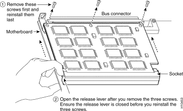
Caution To prevent damage to the SRAM daughter card in the steps that follow, do not open the release lever on the daughter card socket until after you remove the three screws located at the rear of the SRAM daughter card. (See Figure 3-8.) Do not reinstall the three screws until after you install the SRAM daughter card in the socket, and ensure that the release lever is flush against the side of the socket. |
 |
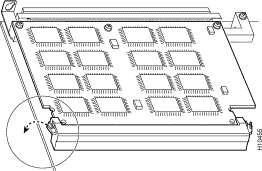
Note Figure 3-9 and Figure 3-10 show the functions of the release lever on the SRAM daughter card socket. To release an SRAM daughter card from the socket, first remove the three screws, and then open the release lever, as shown in . When you insert an SRAM daughter card in the socket, the release lever should close automatically, as shown in Figure 3-10. |
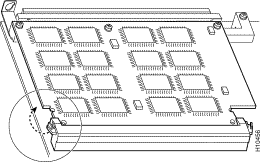
Step 4 Locate the three screws that secure the SRAM daughter card to the motherboard.
(See item 1 in Figure 3-8.)
Step 5 The SRAM daughter card lies parallel to the motherboard when the daughter card connector edge is installed in the socket.
Step 6 Using a number 1 Phillips screwdriver, carefully remove the three screws from the SRAM daughter card (see Figure 3-8), and set them aside.
Step 7 Locate the release lever on the socket. (See Figure 3-8.) Open the release lever to release the SRAM daughter card from the socket.
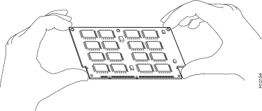
Step 8 When one end of the SRAM daughter card is released from the socket, carefully pull the card away from the socket and motherboard. Handle the edges of the SRAM daughter card only. (See Figure 3-11.)
Step 9 Place the SRAM daughter card in an antistatic container to protect it from ESD damage.
This completes the SRAM daughter card removal procedure. Proceed to the next section to install a new SRAM daughter card.
The SRAM daughter card is a sensitive component that is susceptible to ESD damage. Handle the SRAM daughter card by the edges only; avoid touching the memory modules, pins, or traces
(the metal fingers along the connector edge of the SRAM daughter card). (See Figure 3-11.)
 |
Caution To prevent ESD damage, handle the DIMM as shown in . |
With the DPTIP in the same orientation as the previous procedure (with the handle toward you and the bus connector away from you), install the SRAM daughter card in the socket as described in the following procedure:
Step 2 Hold the SRAM daughter card between your thumbs and forefingers, component side up, with the connector edge (the metal fingers) toward you. (See Figure 3-11.)
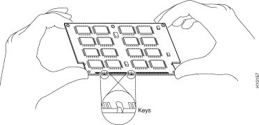
Step 3 Tilt the SRAM daughter card to approximately the same angle as the socket, and insert the connector edge into the socket. Note the two notches (keys) on the connector edge of the SRAM daughter card. (See Figure 3-12.) These keys are intended to ensure correct orientation of the SRAM daughter card in its socket.
 |
Caution When inserting the SRAM daughter card, use firm but not excessive pressure. If you damage a socket, you will have to return the DPTIP to the factory for repair. |
Step 4 Note the orientation of the socket keys on the SRAM daughter card (see Figure 3-12) and the socket, and gently push the SRAM daughter into the socket until the release lever is flush against the side of the socket (see Figure 3-10) and the SRAM daughter card edge connector is fully inserted. If necessary, rock the SRAM daughter card gently back and forth to seat it properly.
 |
Note When the SRAM daughter card is properly inserted in the socket, the three screw holes at the rear of the card should align with the standoffs below the card, and the release lever should be flush against the side of the socket. |
Step 5 Verify that the three screw holes at the rear of the SRAM daughter card align with the standoffs below the SRAM daughter card; using the number 1 Phillips screwdriver, reinstall the three screws. (See Figure 3-8.)
Step 6 After you install the three screws, ensure that the release lever is flush against the side of the socket. (See Figure 3-10.) If it is not, the SRAM daughter card might not be seated properly. If the SRAM daughter card appears misaligned, carefully remove it according to the procedure in the "Removing a DPTIP SRAM Daughter Card" section, and reseat it in the socket. Push the SRAM daughter card firmly back into the socket until the release lever is flush against the side of the socket.
Step 7 Reinstall the DPTIP in your system. (Follow the steps in the section "Interface Processor Removal and Installation" section.
This completes the SRAM daughter card replacement procedure.
If, after an SDRAM or SRAM replacement, the system fails to boot properly, or if the console terminal displays a checksum or memory error, check the following:
![]()
![]()
![]()
![]()
![]()
![]()
![]()
![]()
Posted: Thu Feb 1 17:17:31 PST 2001
All contents are Copyright © 1992--2001 Cisco Systems, Inc. All rights reserved.
Important Notices and Privacy Statement.