Table Of Contents
Product Overview
Product Description
Features and Specifications
Features
Basic Technical Specifications
Additional Features and Characteristics
Front Panel LEDs
Rear Panel Connectors and LEDs
Next Steps
Product Overview
This chapter describes the Cisco uMG9820 QAM Gateway. The chapter contains the following major sections:
• Product Description
• Features and Specifications
• Additional Features and Characteristics
• Next Steps
Product Description
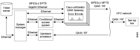
The Cisco uMG9820 QAM Gateway (referred to simply as the Cisco uMG9820) receives MPEG-2 Single Program Transport Streams (SPTSs) encapsulated in UDP/IP datagrams over Gigabit Ethernet (GE). The MPEG-2 SPTS packets are processed and remultiplexed into MPEG-2 Multi Program Transport Streams (MPTSs). The MPTS packets are in turn routed to QAM/RF cards for distribution over the CATV network to downstream connected set-top boxes (STB). (See Figure 1-1.) The QAM cards accept up to four MPTSs, and output up to four QAM-modulated and RF-upconverted signals. The modulation is 256QAM; there are two RF ports per QAM card, and two QAM channels per port.
Figure 1-1 Typical VOD Network using the Cisco uMG9820 QAM Gateway
The Cisco uMG9820 incorporates a number of standard network protocols for management and control, including SNMP for management and configuration, TFTP for firmware upgrades, DHCP for dynamic address assignment, and Telnet for command-line configuration options.
Note HTTP and conditional access system (CAS) are not supported in initial releases.
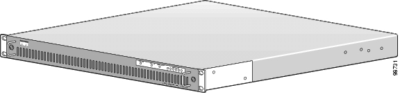
The Cisco uMG9820 is shown in Figure 1-2.
Figure 1-2 Cisco uMG9820 QAM Gateway
Features and Specifications
Features
Table 1-1 summarizes the key operational features of the Cisco uMG9820 QAM Gateway.
Note The chassis is shipped with all components installed. Removal and replacement instructions for all replaceable components are shipped with those components, and are listed in Related Documentation, page viii.
Table 1-1 Key Features of the Cisco uMG9820
Area
|
Feature
|
Comments
|
Operational
|
Modular single rack unit (1RU) chassis supporting online insertion and removal (OIR)
|
Allows addition, replacement, or removal of the QAM cards, power supplies, or fan assembly without interrupting the system.
|
Field-upgradable software
|
Allows remote loading of new images into flash memory.
|
Environmental monitoring and reporting functions
|
Allows maintenance of normal system operation by detecting adverse environmental conditions.
|
Front-to-back airflow
|
Internal fans provide cooling.
|
Chassis
|
One processor card
|
Chassis stores CLEI (Common Language Equipment Identifier) code, system serial numbers, MAC addresses.
|
From 2 (minimum) to 6 QAM cards
|
Two power supplies
|
One fan assembly (with two fans)
|
Processor
|
Redundant 1+1 GE port configuration (one active, one backup)
|
|
One 10BASE-T/100BASE-TX Ethernet port for out-of-band management (NMS—Network Management System)
|
|
One 10BASE-T/100BASE-TX Ethernet port for CAS (conditional access system)
|
For future use.
|
One RS-232 console port for direct serial communications with processor card
|
|
One DVB-ASI monitor port
|
For future use.
|
Configurable user transport stream ID (TSID)
|
|
QAM/RF
|
256QAM modulation
|
|
Two RF ports, two QAM channels per port
|
|
Basic Technical Specifications
Table 1-2 lists the basic technical specifications for the Cisco uMG9820. For the complete technical specifications, see "Cisco uMG9820 Technical Specifications."
Table 1-2 Basic Technical Specifications for the Cisco uMG9820
Characteristic
|
Value
|
Physical
|
Dimensions
|
1.72 in. high x 18.98 in. wide x 21.41 in. deep (43.7 x 444.5 x 342.9 mm)
|
Mounting standard
|
1 RU, 19 in.
|
Weight
|
17.9 lbs (8.1 kg) typical (fully loaded)
|
Electrical
|
Input voltage
|
100-240 VAC
|
Input frequency
|
50-60 Hz
|
Input current
|
3 A max. at 100 VAC input
|
AC power connector
|
IEC 320 standard 6.3-A power entry module, RFI filtered, with metric fuse holder
(a spare 250-V, 6.3-A fuse is in the fuse compartment)
|
Environmental
|
Temperature
|
Operating: 40-104ΉF (10-40ΉC)
|
Nonoperating: -40-158ΉF (-40-70ΉC)
|
Humidity (relative, noncondensing)
|
Operating: 20 to 90%
|
Nonoperating: 5 to 95%
|
Altitude
|
Operating: sea level to 6562 ft (2000 m)
|
Nonoperating: sea level to 15,748 ft (4800 m)
|
Additional Features and Characteristics
Front Panel LEDs
The removable front panel of the Cisco uMG9820 contains status LEDs. Figure 1-3 highlights the LED section of the front panel. Table 1-3 describes the meaning of the LEDs.
Figure 1-3 Cisco uMG9820 Front Panel LEDs
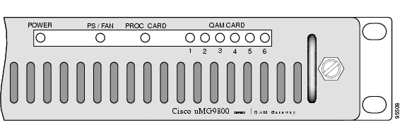
Table 1-3 Front Panel LEDs
LED Label
|
Color
|
State
|
Indication
|
POWER
|
Green
|
On
|
The chassis is powered.
|
Off
|
The chassis is not powered.
|
PS/FAN
|
Bi-color
|
Green
|
No error condition has been detected on the power supplies or the fan assembly.
|
Yellow
|
Either (1) an error condition has been detected on one or both power supplies, (2) an error condition has been detected on the fan assembly, or (3) only one power supply is installed.
|
PROC CARD
|
Bi-color
|
Green
|
No error condition has been detected on the processor card.
|
Yellow
|
An error condition has been detected on the processor card.
|
Yellow, flashing
|
The fan assembly microcontroller has not detected the "heartbeat" signal from the processor card in the last 5 seconds. The processor card is either not installed or there is a communication error.
|
QAM CARD 1 - 6
|
Bi-color
|
Green
|
No error condition has been detected on the corresponding QAM card.
|
Yellow
|
An error condition has been detected on the corresponding QAM card, or the corresponding QAM card is the only one installed.
|
Off
|
No corresponding QAM card is installed.
|
Rear Panel Connectors and LEDs
The rear of the Cisco uMG9820 consists of two separate sections: the QAM modules and the processor module. The rear panel contains connection ports and LEDs, as illustrated below.
Connectors
Figure 1-4 shows the connectors on rear panel of the Cisco uMG9820. The reference numbers in the illustration refer to the explanations in Table 1-4. For slot and port numbering, see Slot and Port Logical Interface Numbering.
Figure 1-4 Cisco uMG9820 Rear Panel
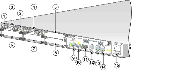
Table 1-4 Rear Panel Connectors
Ref. No.
|
Connector Label
|
Function
|
1
|
Various
|
RF output (downstream) cable interface, 75-ohm F-connector. There are two RF ports per QAM module, labeled DS1 and DS2. A label on the processor module identifies the locations of QAM module slots 1 through 6.
|
2
|
Various
|
RF monitor interface (MCX connector). The interface for RF port DS1 is labeled TEST 1, and the interface for DS2 is labeled TEST 2.
|
9, 10
|
GIG1, GIG2
|
Gigabit Ethernet (GE) ports 1 and 2, respectively, accept MPEG-2 SPTS from a VoD server. GIG1 (GE port 1) is the active port, and GIG2 (GE port 2) is standby with automatic fail-over. These ports share a common IP and MAC address. Each port uses an industry-standard small form-factor pluggable (SFP) module.
|
11
|
ASI MON
|
BNC connector with factory-installed cap. For future use.
|
12
|
CONSOLE
|
RJ-45 connector port—Provides direct serial communications with the processor card.
|
13
|
FE1 (NMS)
|
Network Management System port, RJ-45 connector port—Provides a direct Fast Ethernet link for out-of-band management traffic.
|
14
|
FE2 (CAS)
|
Conditional Access System port, RJ-45 connector port—Provides a direct Fast Ethernet link for conditional access traffic.
|
15
|
Power
|
AC power input
|
Slot and Port Logical Interface Numbering
Interfaces are addressed in the command line interface (CLI) software by type, slot number, and port number. For the QAM interfaces, the QAM channel also is identified. The number of physical ports depends on the type of modular port adapter or fixed interface. For example, Fast Ethernet 0/1 indicates Fast Ethernet port 1 on the processor card in slot 0. For further information on interface addressing, see "Starting and Configuring the Cisco uMG9820"
Slots and ports in the Cisco uMG9820 are numbered as shown in Table 1-5. The reference numbers in the table refer to Figure 1-4.
Table 1-5 Slot and Port Numbers
Ref. No.
|
Function
|
3, 4, 5, 6, 7, 8
|
Slot 1 through 6—QAM card interfaces
|
9
|
Gigabit Ethernet port 1
|
10
|
Gigabit Ethernet port 2
|
11
|
ASI port 1 (not active-for future use)
|
12
|
Console port
|
13
|
Fast Ethernet port 1
|
14
|
Fast Ethernet port 2
|
LEDs
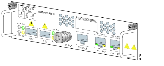
Figure 1-5 highlights the LED section of the rear panel of the Cisco uMG9820. Table 1-6 describes their meaning.
Note For a detailed discussion of the behavior of some LEDs, see Subsystem Troubleshooting Tips.
Figure 1-5 Cisco uMG920 Rear Panel LEDs
Table 1-6 Rear Panel LEDs
Port
|
LED Label
|
Color
|
State
|
Indication
|
GE
|
ALM
|
Red
|
On
|
Noncritical errors exist on the GE link:
•rate of PHY errors above threshold
•rate of CD errors above threshold
•rate of RX packets with errors above threshold
•rate of TX packets with errors above threshold
Note PHY, CD, RX packet, and TX packet errors are defined in the IEEE 802.3z standard. The user cannot set the definitions and thresholds for these errors, as they are dictated by the standard.
|
ERR
|
Red
|
On
|
Critical errors exist on the GE link:
•TX underrun
•RX overflow
|
LNK
|
Green
|
On
|
The GE link is up.
|
ACT
|
Yellow
|
On
|
There is activity on the GE link.
|
FE
|
LNK
|
Green
|
On
|
The 10BASE-T/100BASE-TX FE link is up.
|
ACT
|
Yellow
|
On
|
There is activity on the 10BASE-T/100BASE-TX FE link.
|
Grounding
This product is grounded through the ground wire in the AC power cord. There is no separate ground connection.
Next Steps
After becoming familiar with the Cisco uMG9820, proceed as follows to prepare and complete the installation and startup of the unit:
1. Before installing the Cisco uMG9820, review Chapter 2, "Preparing for Installation,", to determine site-planning considerations and steps.
2. Install and cable the Cisco uMG9820, following the steps in Chapter 3, "Installing the Cisco uMG9820."
3. Start up and use the CLI to configure the Cisco uMG9820, following the instructions in "Starting and Configuring the Cisco uMG9820"
4. If any problems are encountered during the installation, startup, or configuration of the Cisco uMG9820, consult "Troubleshooting"