|
|

Table Of Contents
Starting and Configuring the Cisco uMG9820
Checking Conditions Prior to System Startup
Configuring the Transport Stream
Configuring and Monitoring QAM Service
Using the Terminal (Console) Port
Using the Terminal (Console) Port
Starting and Configuring the Cisco uMG9820
This chapter describes how to start the system and initially configure your Cisco uMG9820. The chapter presents the following major topics:
•
Checking Conditions Prior to System Startup
In addition, for a sample running configuration file, see the following:
Note
Checking Conditions Prior to System Startup
Ensure the following before you start your Cisco uMG9820:
•
•
•
•
•
•
•
Starting the System
After installing the Cisco uMG9820 and connecting required cables, start the Cisco uMG9820 as follows:
Step 1
The green power (POWER) LED on the Cisco uMG9820 comes on.
Step 2
Step 3
The front panel LEDs (PS/FAN, PROC, and QAM 1 through 6) transition from off to yellow, then to green, and then to the functionality as described in Table 1-2. If the processor card is not installed on power-up, all LEDs (except the POWER LED) default to off.
Note
Step 4
The LNK LED on each processor card interface comes on when initialization is completed, and the console screen displays a system banner similar to the following:Enter <CTRL D> to stop Operating System auto-boot:..... 1Uncompressing Operating System kernel image file....................................doneStarting kernel ..........RAMDISK: gzip compressed image found at block 0Thu Apr 8 12:36:52 2004Bootloader Image File Version : 0.0.12Ramdisk Image File Version : 1.3.0Ramdisk Build Date : Thu Apr 1 14:09:19 CST 2004Kernel Image File Version : 0.2.10Initializing system..............................doneStarting automatic software upgrade...Available software upgrade does not differ from previous upgrade...No action taken% Shell v1.3.0uMG9820>Step 5
Step 6
Configuration Tasks
This section presents the following:
•
•
•
•
Command Syntax
General syntax and the basic provisioning areas are discussed below:
Syntax Overview
Commands use the following general syntax, where variables are in italics and command names and keywords are in bold:
Hostname(mode)# [no] keyword {keyword1 argument1 | keyword2 argument2 | ...} [keyword1 argument1 | keyword2 argument2 | ...], where Hostname and mode are variables, as follows:
Hostname—Is the user-settable name for the unit. In this document, uMG9820 is used in all examples.
•
–
–
–
–
•
•
–
–
–
–
Ethernet Interfaces
Ethernet interfaces are addressed as follows:
slot/port
where slot is always zero (0) for Ethernet interface ports. The keywords for Ethernet interface ports are as follows:
•
•
QAM Ports
The QAM ports are addressed by means of subinterface notation, as follows:
slot/port
.qamwith the variables defined below:
•
•
•
ASI Interface
The ASI output interface is configured by means of the keyword asi.
Note
Console Port Interface
The RS-232 console port is configured by means of the terminal command in configuration mode.
Configuring Passwords
This section covers commands for the following operations:
•
•
Enabling and Disabling Passwords for Configuration Mode
To specify and enable or disable the configuration mode password:
uMG9820(config)#[no] enable password passwordwhere
password = Text string for the password
Example—Set password for entering terminal configuration mode to "cisco":
uMG9820(config)#enable password ciscoExample—Disable password requirement for entering terminal configuration mode:
uMG9820(config)#no enable passwordConfiguring a Telnet Password
To specify and enable or reset the system Telnet password:
uMG9820(config)#[no] line vty password passwordwhere
password = Text string for the password
Note
Example—Set the password for entering configuration mode when using Telnet to "cisco":
uMG9820(config)#line vty password ciscoExample—Set the password for entering configuration mode when using Telnet to the default value:
uMG9820(config)#no line vty password
Note
Configuring GE Ports
This section covers commands for the following operations on the ports labeled GIG1 and GIG2:
•
•
•
Enabling and Disabling a GE Port
To enable and disable a GE port:
uMG9820(config-if)#[no] shutExample—Enable GE port 1:
uMG9820# configure terminaluMG9820(config)# interface gigabitethernet 0/1uMG9820(config-if)#no shutExample—Switch active GE port from 1 to 2:
Note
uMG9820# configure terminaluMG9820(config)# interface gigabitethernet 0/1uMG9820(config-if)#shutuMG9820(config-if)#exituMG9820(config)# interface gigabitethernet 0/2uMG9820(config-if)#no shut
Note
Setting GE Port IP Address and Subnet Mask
To set the IP address and subnet mask for a GE port:
uMG9820(config-if)#ip address IP address subnet maskwhere
IP address = Text string for standard IP address
subnet mask = Text string for standard subnet mask
Example—Set IP address to 192.168.0.10 and subnet mask to 255.255.255.0 for GE port 1:
uMG9820# configure terminaluMG9820(config)# interface gigabitethernet 0/1uMG9820(config-if)#ip address 192.168.0.10 255.255.255.0
Note
Setting GE Port MAC Address
To set the IP address for a GE port:
uMG9820(config-if)#mac-address MAC addresswhere
MAC address = Text string for standard MAC address in H.H.H format
Example—Set the MAC address to 0000.0123.5678 for GE port 1:
uMG9820# configure terminaluMG9820(config)# interface gigabitethernet 0/1uMG9820(config-if)#mac-address 0000.0123.5678
Note
Providing Redundancy for Failover
Both GE ports share the same IP and MAC addresses. This facilitates failover in scenarios requiring 1+1 redundancy. To provide for failover between a VoD server and the Cisco uMG9820, you need to split the VoD content stream into two identical streams and feed each stream to a GE port.
Retrieving GE Statistics
To display packet and buffer statistics for the specified GE port:
uMG9820#show interface gigabitethernet slot/portwhere
slot = 0
port = 1 or 2
Example—Show the SFP module and hardware data for GE port 1:
uMG9820# show interface gigabitethernet 0/1GigabitEthernet 0/1 is up, line state is cable not installed.Hardware is Gigabit Ethernet Port, address is 0050.c206.e2c3IP address is 192.168.145.93Full-duplex, 1000Mb/s0 packets input, 0 bytesReceived 0 broadcasts (0 multicast)0 runts, 0 giants0 input errors, 0 CRC, 0 overrun0 packets output, 0 bytes0 output errorsRetrieving GE Port Status
To display the status of the specified GE port:
•
•
uMG9820#show ip interface [brief] gigabitethernet slot/portwhere
brief = Optional keyword to display link status only
slot = 0
port = 1 or 2
Example—Show the status of GE port 1:
uMG9820#show ip interface gigabitethernet 0/1GigabitEthernet 0/1 is down, line state is no module installed.Inbound access list is not setExample—Show only the link status of GE port 1:
uMG9820#show ip interface brief gigabitethernet 0/1Interface IP-address OK Method Status ProtocolGigabitEthernet0/1 192.168.1.34 NO Manual Up DownTo see the status of all Ethernet ports, use the following command:
Example—Show the status of all Ethernet ports:
uMG9820#show ip interfaceFastEthernet 0/1 is UpInternet address is 192.168.145.130, subnet mask is 255.255.255.0Broadcast address of 192.168.145.255 is validMTU is 1500 bytes, Metric is 1FastEthernet 0/2 is UpInternet address is 64.13.20.160, subnet mask is 64.13.20.160Broadcast address of 64.13.20.160 is validMTU is 1500 bytes, Metric is 1GigabitEthernet 0/1 is up, line state is cable not installed.Inbound access list is not setGigabitEthernet 0/2 is down, line state is no module installed.Inbound access list is not setExample—Show only the link status of all Ethernet ports:
uMG9820#show ip interface briefInterface IP-address OK Method Status ProtocolFastEthernet0/1 192.168.145.130 YES DHCP Up UpFastEthernet0/2 64.13.20.160 YES DHCP Up DownGigabitEthernet0/1 192.168.1.34 NO Manual Up DownGigabitEthernet0/2 0.0.0.0 NO Manual Administratively Down Down
Note
uMG9820(config)#clear counters
Using GE Session Commands
This section covers commands for the following operations:
•
•
•
•
•
Setting the UDP Port Assignment
There are two ways to set the UDP port assignment:
Tip
Default Method
The UDP port is a 16-bit number of the form QQQQQQQQ PPPPPPPP, with a valid range of 0x0100 through 0x18FF, where the bytes are defined as follows:
•
•
•
Note
Table 4-1 shows the mappings between the QAM subinterfaces and channels and the UDP ports. All port ranges for each channel are from 1 through 255 (00000001-11111111). Program 0 is represented by numbers such as 256, 512, 768, ... 6144.
User-Defined Method
You can override the default UDP port mapping for individual QAM channels by specifying the starting UDP port, the increment (sequential or even), and the total number of ports to map. For example, if the starting UDP port is 0x4000, the increment is even, the total number of ports to map is 0x9, and QAM channel 1 is targeted, then UDP ports 0x4000, 0x4002, 0x4004, 0x4006, 0x4008, 0x400A, 0x400C, 0x400E, and 0x4010 are mapped to QAM channel 1.
uMG9820(config-subif)#[no]video udp UDP-port-number {program program-number
[use {even| sequential} count]}where
UDP-port-number = UDP port number of the desired incoming session to be mapped
If a range is being defined, this number acts as the initial value in the series. Subsequent values are incremented according to either an even or a sequential numbering scheme, as specified by the user.
program-number = Output program number that the sessions are mapped to
If a range is being defined, this number also acts as the initial value in the series. Subsequent values are incremented according to the same numbering sequence as the UDP port number (even or sequential).
use {even | sequential} = Type of sequence to be used for UDP port and program numbering
use even = increment value by two; use sequential = increment value by one
count = Number of UDP ports to be mapped to this QAM channel
Example—Map incoming session on UDP port 5201 to program 10 on slot 1, port 1, QAM channel 2:
uMG9820# configure terminaluMG9820(config)# interface qam 1/1.2uMG9820(config-subif)#video udp 5201 program 10Example—Map incoming sessions on UDP ports 8201, 8203, 8205, and 8207 to program numbers 2, 4, 6, and 8, respectively, on slot 1, port 1, QAM channel 2:
uMG9820# configure terminaluMG9820(config)# interface qam 1/1.2uMG9820(config-subif)#video udp 8201 program 2 use even 4Example—Remove mapping of UDP ports 8201 to program number 2 on slot 1, port 1, QAM channel 2:
uMG9820# configure terminaluMG9820(config)# interface qam 1/1.2uMG9820(config-subif)#no video udp 8201 program 2Example—Revert all mapping of UDP ports on slot 1, port 1, QAM channel 2 to default mapping behavior:
uMG9820# configure terminaluMG9820(config)# interface qam 1/1.2uMG9820(config-subif)#no video udpSpecial Issues: UDP
Note the following special issues related to UDP:
1.
2.
3.
4.
5.
The implication of this is that QAM channel loading is entirely the responsibility of the end user to manage. Suppose the following:
–
–
–
If an 11th SPTS/UDP port session is requested on that QAM channel, and its addition exceeds the total bandwidth (38.81071 Mbps), then all programs in that channel will be randomly corrupted (their packets dropped) until the bandwidth is reduced by (a) removing a session, or (b) reducing the bandwidth required by one or more sessions.
In summary, the user is responsible for bandwidth management. Although the user can request up to 16 sessions per QAM channel, the total bandwidth for the channel cannot be exceeded. Otherwise, MPEG packets will be randomly dropped from all the sessions on that block. For example, a user can put 16 low-bandwidth (< 2.4 Mbps) sessions on one 256QAM channel, with no problem. However, if the user puts three HDTV (15 Mbps x 3 = 45 Mbps) sessions on that channel all three programs will be randomly corrupted.
6.
Setting Session Timeouts
To set session timeouts for the GE ports:
uMG9820(config-if)#[no] video timeout {inactive inactive-time | release release-time | queue deallocation-time}where
inactive-time = Mark sessions as "inactive" if they have not received an IP packet for inactive-time in milliseconds
The default value for inactive-time is the maximum network jitter value (set by user; see Setting Maximum Network Jitter) plus 100 milliseconds.
release-time = Remove system resources and outgoing PSI program references for sessions that have gone to an "inactive" state after release-time in seconds
The default value for release-time is 5 seconds.
deallocation-time = Deallocate system resources for sessions that have gone to an "inactive" state for deallocation-time in seconds
The default value for deallocation-time is 5 minutes.
Example—Set inactive time to 500 milliseconds for all sessions on GE port 1:
uMG9820# configure terminaluMG9820(config)# interface gigabitethernet 0/1uMG9820(config-if)#video timeout inactive 500Example—Set release time to 10 seconds for all sessions on GE port 1:
uMG9820# configure terminaluMG9820(config)# interface gigabitethernet 0/1uMG9820(config-if)#video timeout release 10Example—Set deallocation time for the queue to 4 minutes for all sessions on GE port 1:
uMG9820# configure terminaluMG9820(config)# interface gigabitethernet 0/1uMG9820(config-if)#video timeout queue 240Example—Set inactive time to default value for all sessions on GE port 1:
uMG9820# configure terminaluMG9820(config)# interface gigabitethernet 0/1uMG9820(config-if)#no video timeout inactiveExample—Set release time to default value for all sessions on GE port 1:
uMG9820# configure terminaluMG9820(config)# interface gigabitethernet 0/1uMG9820(config-if)#no video timeout releaseSetting Maximum Network Jitter
To set the maximum allowable network jitter (packet latency) for the specified UDP port session:
Note
uMG9820(config-if)#[no] video udp UDP-port-number jitter jitter-valuewhere
UDP-port-number = UDP port number of the desired incoming session for which the maximum network jitter is to be set.
jitter-value = Maximum network jitter value in milliseconds. The jitter value may be set in the range of 10 to 250 milliseconds.
The default jitter-value is 100 milliseconds.
Example—Set maximum network jitter value for UDP port 5201 to 250 milliseconds for GE port 1:
uMG9820# configure terminaluMG9820(config)# interface gigabitethernet 0/1uMG9820(config-if)#video udp 5201 jitter 250Example—Set maximum network jitter value for UDP port 5201 to default value for GE port 1:
uMG9820# configure terminaluMG9820(config)# interface gigabitethernet 0/1uMG9820(config-if)#no video udp 5201 jitterSetting PID Remapping
To remap or drop PIDs within an incoming UDP port session:
uMG9820(config-if)#[no] video UDP UDP-port-number in PID-number {out PID-number | drop}where
UDP-port-number = UDP port number of the desired incoming session that contains the PID to be remapped
in PID-number = PID number to be remapped or dropped
out PID-number = New PID number (in decimal) in the outgoing program
Example—Remap incoming PID 1000 on UDP port 5201 to PID 1001 for GE port 1:
uMG9820# configure terminaluMG9820(config)# interface gigabitethernet 0/1uMG9820(config-if)#video udp 5201 in 1000 out 1001Example—Drop incoming PID 1000 on UDP port 5201 for GE port 1:
uMG9820# configure terminaluMG9820(config)# interface gigabitethernet 0/1uMG9820(config-if])#video udp 5201 in 1000 dropExample—Handle PIDs on UDP port 5201 in default manner for GE port 1:
uMG9820# configure terminaluMG9820(config)# interface gigabitethernet 0/1uMG9820(config-if)#no video udp 5201Binding a UDP Port to a VoD Server
Where multiple VoD servers are used, it is possible for video session streams to collide on the same UDP port of the Cisco uMG9820. This can be prevented by using source address filtering (on the addresses of the VoD servers) to prevent collisions. The user is responsible for ensuring that only one VoD server in a multiserver installation is actually streaming video to a given UDP port at any time.
Note
Use the command allow in interface configuration mode, as illustrated below.
To bind a UDP port to a VoD server:
uMG9820(config-if)#[no] allow udp UDP-port-number IP-addressExample—Binding UDP Port 6600 to VoD Server Address 172.16.0.6:
uMG9820# configure terminaluMG9820(config)# interface gigabitethernet 0/1uMG9820(config-if)#allow udp 6600 172.16.0.6Example—Unbinding UDP Port 6600 from VoD Server Address 172.16.0.6:
uMG9820# configure terminaluMG9820(config)# interface gigabitethernet 0/1uMG9820(config-if)#no allow udp 6600 172.16.0.6Retrieving Input Session Data
To list all the session information, input errors, session state, and continuity count errors:
uMG9820#show interface gigabitethernet slot/port video [session UDP-port-number]where
slot = 0
port = 1 or 2
UDP-port-number = Number of specific UDP port (optional)
If a specific session UDP port number is provided, then only information on that session is provided. The following information is provided in the response:
•
•
•
•
Example—Display all active video sessions on GE port 1:
uMG9820# show interface gigabitethernet 0/1 videoNumber of active sessions 0Source Continuity Error Counter 0Example—Display video session information for UDP port 257 on GE port 1:
uMG9820# show interface gigabitethernet 0/1 video session 257Current State : ActiveUDP port number : 257 Output QAM number : 0Max Jitter Value : 0 Jitter Overflow : 0Jitter Underflow : 0 Average Fullness : 0Continuity Errors : 0
Note
uMG9820(config)#clear counters
Retrieving Input Session PSI Data
To list all the Program Specific Information (PSI), such as program number, elementary stream ID and PIDs, for a video session:
uMG9820#show interface gigabitethernet slot/port video psi [session UDP-port-number]where
slot = 0
port = 1 or 2
UDP-port-number = Number of specific UDP port (optional)
If a specific session UDP port number is provided, then only information on that session is provided.
Example—Display PSI information for all active video sessions on GE port 1:
uMG9820# show interface gigabitethernet 0/1 video psiInactive PSI Timeout is 0 seconds.Active PSI Timeout is 5 seconds.Queued PSI Timeout is 300 seconds.Example—Display PSI information for UDP port 5401 on GE port 1:
uMG9820# show interface gigabitethernet 0/1 video psi session 5401Number of PIDs : 3 Program Number : 1Input PMT PID : 501 Output PMT PID : 32Input PID (Type 81) : 273 Output PID : 33Input PID (Type 3) : 274 Output PID : 34Input PID (Type 2) : 272 Output PID : 35Configuring Management Ports
The management and CAS ports are addressed using the CLI as Fast Ethernet (FE) ports 1 and 2, respectively. This section covers commands for the following operations:
•
•
•
•
•
Enabling and Disabling an FE Port
To enable and disable an FE port:
uMG9820(config-if)#[no] shutChanges to an FE port's state take effect immediately.
Note
Example—Enable FE port 1:
uMG9820# configure terminaluMG9820(config)# interface fastethernet 0/1uMG9820(config-fastethernet[0/1])#no shutExample—Disable FE port 1:
uMG9820# configure terminaluMG9820(config)# interface fastethernet 0/1uMG9820(config-if)#shutSetting an FE Port IP Address
To set the IP address and subnet mask of an FE port:
uMG9820(config-if)#ip address IP-address subnet-maskwhere
IP-address = Text string for standard IP address
subnet-mask = Text string for standard subnet mask
Changes to an FE port's IP address take effect immediately.
Example—Set the IP address to 192.168.0.10 and subnet mask to 255.255.255.0 for FE port 1:
uMG9820# configure terminaluMG9820(config)# interface fastethernet 0/1uMG9820(config-if)#ip address 192.168.0.10 255.255.255.0Setting an FE Port MAC Address
To set the MAC address for an FE port:
uMG9820(config-if)#mac-address MAC-addresswhere
MAC-address = Text string for a standard MAC address in H.H.H form
Changes to an FE port's MAC address take effect following a reload only if the change is first written to the startup configuration. See Managing Configurations.
Example—Set the MAC address to 0000.0123.5678 for FE port 1:
uMG9820# configure terminaluMG9820(config)# interface fastethernet 0/1uMG9820(config-if)#mac-address 0000.0123.5678Setting an FE Port in DHCP Mode
To instruct the FE port to obtain its IP address information from a Dynamic Host Configuration Protocol (DHCP) server:
uMG9820(config-if)#[no] dhcpChanges to DHCP mode are immediate. When DHCP is disabled, the IP address reverts to the manually specified value.
Example—Enable DHCP mode for FE port 1:
uMG9820# configure terminaluMG9820(config)# interface fastethernet 0/1uMG9820(config-if)#dhcpExample—Disable DHCP mode for FE port 1:
uMG9820# configure terminaluMG9820(config)# interface fastethernet 0/1uMG9820(config-if)#no dhcpSetting the Default Gateway
To set the IP address of the default gateway for FE ports:
uMG9820(config-fastethernet[slot/port])# ip default-gateway IP-addresswhere
IP-address = Text string for a standard IP address
Example—Set the default gateway address to 192.168.0.1 for FE port 1:
uMG9820# configure terminaluMG9820(config)# interface fastethernet 0/1uMG9820(config-if)#ip default-gateway 192.168.0.1Setting Boot Mode
By default, the system boots from internally stored images. However, it is possible to specify the location of the system and kernel images on a remote file system and enable/disable BootP (bootstrap protocol) mode. These files are obtained over an FE management port.
To enable BootP mode, images, and paths:
uMG9820(config-fastethernet[0/1])#[no] boot {system path | kernel path}where
system path = Remote-system file path for the system image
kernel path = Remote-system file path for the kernel image
Example—Enable BootP mode:
uMG9820# configure terminaluMG9820(config)# interface fastethernet 0/1uMG9820(config-if)#bootExample—Set BootP system path to "ramdisk_img.gz":
uMG9820# configure terminaluMG9820(config)# interface fastethernet 0/1uMG9820(config-if)#boot system ramdisk_img.gzExample—Set BootP kernel path to "zImage":
uMG9820# configure terminaluMG9820(config)# interface fastethernet 0/1uMG9820(config-if)#boot kernel zImageExample—Disable BootP mode:
uMG9820# configure terminaluMG9820(config)# interface fastethernet 0/1uMG9820(config-if)#no bootRetrieving FE Port Statistics
To retrieve packet and buffer statistics for an FE port:
uMG9820#show interface fastethernet slot/portwhere
slot = 0
port = 1 or 2
Example—Show packet and buffer statistics for FE port 1:
uMG9820#show interface fastethernet 0/1FastEthernet0/1 Link Encapsulation:Ethernet HW Address 0050.c206.c299IP Address:192.168.145.130 Broadcast:192.168.145.255 Netmask:255.255.255.0RX Packets:88 Errors:0 Dropped:0 Overruns:0 Frame:0TX Packets:6 Errors:0 Dropped:0 Overruns:0 Carrier:0Collisions:0 TX Queue Length:100RX bytes:11406 (11.1 kb) TX bytes:913 (913.0 b)Interrupt:14Gateway:192.168.145.1 DHCP:Enabled BootP:DisabledRetrieving FE Port Status
To retrieve the status of an FE port:
uMG9820#show ip interface [brief] fastethernet slot/portwhere
brief = Optional keyword to display link status only
slot = 0
port = 1 or 2
You can retrieve the following IP statistics for the specified FE port:
•
•
Example—Show the status of FE port 1:
uMG9820#show ip interface fastethernet 0/1FastEthernet 0/1 is UpInternet address is 192.168.145.130, subnet mask is 255.255.255.0Broadcast address of 192.168.145.255 is validMTU is 1500 bytes, Metric is 1Example—Show only the link status of FE port 1:
uMG9820#show ip interface brief fastethernet 0/1Interface IP-address OK Method Status ProtocolFastEthernet0/1 192.168.145.130 YES DHCP Up Up
Tip
Note
uMG9820(config)#clear counters
Configuring the Transport Stream
MPEG-2 Program Specific Information (PSI) uses a variety of messages to inform the MPEG receiver about the content of the program stream, and about the streams that are available within the network.
These commands are applied in subinterface mode to an individual QAM channel,
where
slot = 0, 1, 2, 3, 4, 5, or 6
port = 1 or 2
qam = 1 or 2
Table 4-2 lists the MPEG messages and message components that are addressed by the CLI.
Table 4-2 MPEG Messages and Message Components Addressed by the CLI
PAT (Program Association Table)
The first message the receiver attempts to acquire from an MPEG stream. The PAT contains a list of the programs in the stream, as well as a pointer to the PMT for each (see below). It also includes the transport stream ID, or TSID. (See Table 4-3.)
PMT (Program Map Table)
A message that describes the elements of a program. Each program has its own PMT. Once a receiver has acquired a PMT message, it has the information needed to find different elements (for example, video and audio) for that program within the stream.
NIT (Network Information Table)
A list of all of the transport streams within the network, along with their associated RF frequencies. The NIT is identified by means of a network-shared NIT ID (NIT PID). This allows the receiver to know what streams are available. (NIT messages are not always present.)
Table 4-3 shows the default TSID assignment for each QAM channel (subinterface).
This section covers commands for the following operations:
•
•
Setting PAT Message Parameters
To set the message field parameters for the outgoing PAT message:
uMG9820(config-subif)#[no] video pat {interval time | tsid tsid | nit-pid pid}where
time = maximum interval, in milliseconds, between PAT messages
The default value for time is 100 milliseconds.
tsid = Transport stream ID for the output going PAT message. The default value must be unique for each transport stream.
pid = Reference to the NIT PID value in program zero of the PAT message.
The default is to have no reference program zero (program0, which is the NIT PID) in the PAT message.
Example—Set maximum PAT interval to 500 milliseconds on slot 1, port 1, QAM channel 2:
uMG9820# configure terminaluMG9820(config)# interface qam 1/1.2uMG9820(config-subif)#video pat interval 500Example—Set the TSID field of the PAT message to 2250 on slot 1, port 1, QAM channel 2:
uMG9820# configure terminaluMG9820(config)# interface qam 1/1.2uMG9820(config-subif)#video pat tsid 2250Example—Include program 0 with a reference to PID 4090 in the PAT on slot 1, port 1, QAM channel 2
uMG9820# configure terminaluMG9820(config)# interface qam 1/1.2uMG9820(config-subif)#video pat nit-pid 4090Example—Remove program 0 from the PAT message on slot 1, port 1, QAM channel 2:
uMG9820# configure terminaluMG9820(config)# interface qam 1/1.2uMG9820(config-subif)#no video pat nit-pidSetting PMT Message Interval
To set the maximum PMT message interval:
uMG9820(config-subif)#[no] video pmt interval timewhere
time = Maximum interval, in milliseconds, between PMT messages
The default value for time is 100 milliseconds.
Example—Set maximum PMT interval to 500 milliseconds on slot 1, port 1, QAM channel 2:
uMG9820# configure terminaluMG9820(config)# interface qam 1/1.2uMG9820(config-subif)#video pmt interval 500Configuring and Monitoring QAM Service
This section covers commands for the following operations:
•
•
These commands are applied in subinterface mode to an individual QAM channel,
where
slot = 1, 2, 3, 4, 5, or 6
port = 1 or 2
qam = 1 or 2
Enabling and Disabling a QAM Channel
To enable or disable (mute) a QAM channel:
uMG9820(config-subif)#[no] shut
Note
Example—Enable QAM output on slot 1, port 1, QAM channel 2:
uMG9820# configure terminaluMG9820(config)# interface qam 1/1.2uMG9820(config-subif)#no shutExample—Disable QAM output on slot 1, port 1, QAM channel 2:
uMG9820# configure terminaluMG9820(config)# interface qam 1/1.2uMG9820(config-subif)#shutSetting QAM Modulation
To set the modulation rate for all QAM outputs on the selected QAM card:
uMG9820(config-subif)#[no] video format typewhere
type = Modulation scheme. Values are either 64QAM or 256QAM.
The default value for type is 256QAM.
Note
Example—Set the modulation rate for all QAM outputs on slot 1, port 1, QAM channel 2 to 256QAM:
uMG9820# configure terminaluMG9820(config)# interface qam 1/1.2uMG9820(config-subif)#video format 256QAMExample—Set the modulation rate for all QAM outputs on slot 1, port 1, QAM channel 2 to default value:
uMG9820# configure terminaluMG9820(config)# interface qam 1/1.2uMG9820(config-subif)#no video formatSetting QAM Frequency
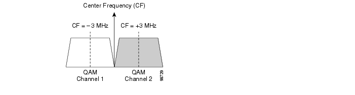
Figure 4-1 illustrates the QAM channel 1 and channel 2 frequencies in relation to the center frequency.
Figure 4-1 QAM Channel Frequencies
To set the center frequency of the selected QAM channel:
uMG9820(config-subif)#video frequency frequencywhere
frequency = QAM channel center frequency in Hz, from 225000000 to 900000000.
Note
Caution
Example—Set the center frequency of slot 1, port 1, QAM channel 1 to 850 MHz:
uMG9820# configure terminaluMG9820(config)# interface qam 1/1.1uMG9820(config-subif)#video frequency 850000000
Note
Special Issues: Selecting QAM Frequencies to Avoid Overlap
The frequencies on an RF chain (or block: the circuitry providing the maximum bandwidth of a QAM port—from 3 MHz below the bottom center frequency to 3 MHz above the top center frequency) must not overlap those of the other port on the same QAM card. (For this discussion, the two ports on the same card are referred to as adjacent ports.) The settings of the QAM frequencies (center frequencies) on each channel determine the upper and lower bounds of the RF chain.
Note
Note the following rules for selecting QAM frequencies (center frequencies):
1.
2.
Caution
3.
Table 4-4 lists both invalid (examples 1 and 2) and valid (examples 3 and 4) QAM center frequency schemes. For an explanation of each example, see the Notes following the table.
Note
•
•
Notes
•
•
•
•
•
•
Setting QAM Output Power
To set the combined output power level for a QAM port:
uMG9820(config-subif)#video power powerwhere
power = QAM power assignment in dBmV. The value can be from 50 to 60, in one-unit increments.
Example—Set the output power level of slot 1, port 1, QAM channel 1 to 50 dBmV:
uMG9820# configure terminaluMG9820(config)# interface qam 1/1.1uMG9820(config-subif)#video power 50
Note
Retrieving QAM Statistics
To display QAM statistics for a specified QAM channel:
uMG9820#show interface qam slot/port.qamwhere
slot = 1, 2, 3, 4, 5, or 6
port = 1 or 2
qam = 1 or 2
Example—Show QAM statistics for slot 1, port 1, QAM channel 1:
uMG9820#show interface qam 1/1.1Output Frequency : 249000000 HzOutput RF Power Level : 46.0 dBmV Output RF Attenuation : 19.6 dBPort Enable : Enabled Channel Enable : EnabledQAM Mode : 256 Encode State : Annex BInterleaver Depth : 128,1 Bytes per packet : 188Gain Compensation : Active RF block ALC setting : EnabledRF block ALC power : 46.0 dBmV Temperature : 46.0C +/- 3CAlarm Codes :Retrieving QAM Output Video Data
To display video program data for a specified QAM channel:
uMG9820#show interface qam slot/port.qam videowhere
slot = 1, 2, 3, 4, 5 or 6
port = 1 or 2
qam = 1 or 2
The following information is retrieved:
•
•
•
•
Example—Show video program data for slot 1, port 1, QAM channel 1:
uMG9820#show interface qam 1/1.1 videoTSID: 111 NIT-PID: 0 PAT Interval: 100 PMT Interval: 100Average Bitrate: 0 bpsProgram (INACTIVE): 0Program (INACTIVE): 0Program (INACTIVE): 0Program (INACTIVE): 0Program (INACTIVE): 0Program (INACTIVE): 0Program (INACTIVE): 0Program (INACTIVE): 0Program (INACTIVE): 0Program (INACTIVE): 0Program (INACTIVE): 0Program (INACTIVE): 0Program (INACTIVE): 0Program (INACTIVE): 0Program (INACTIVE): 0Program (INACTIVE): 0Upgrading Software
This section covers commands for the following operation:
•
Initiating a Software Upgrade from a File Server
To configure and perform an upgrade from a remote server:
uMG9820#upgrade {server ip address | filename remote filename | now {force }}where
server ip address = IP address of the server where the upgrade files are stored
remote filename = Name of the upgrade file stored on the remote system
now = Perform the software upgrade if the specified file has a higher version number than that of software currently installed
force = Perform the software upgrade to the specified file, regardless of software version
Example—Specify 192.168.3.7 as the IP address of the server where the upgrade software resides:
uMG9820#upgrade server 192.168.3.7Example—Specify "newsoftware.tar" as the upgrade filename:
uMG9820#upgrade filename newsoftware.tarExample—Upgrade to the new software immediately:
uMG9820#upgrade nowExample—Upgrade to the new software immediately, even if it is older than the currently installed version:
uMG9820#upgrade now forceManaging Configurations
This section covers commands for the following operations:
•
•
•
•
•
Saving a Running Configuration to the Startup Configuration
To save the current running-configuration settings to a storage location for the startup-configuration settings (except for the case where a BootP configuration is used):
uMG9820#copy running-config startup-configwhere
running-config = Current running configuration settings (in RAM)
startup-config = Stored configuration settings that are loaded at startup
Example—Copy the running configuration settings to the startup configuration file:
uMG9820#copy running-config startup-configRestoring the Startup Configuration to the Running Configuration
To load the stored startup-configuration settings to the running configuration settings (overwriting current running-configuration settings, and appending changes to the file):
uMG9820#copy startup-config running-configwhere
running-config = current running-configuration settings
startup-config = stored configuration settings that are loaded at startup
Example—Copy the stored startup configuration settings to the running configuration:
uMG9820#copy startup-config running-configSaving a Configuration to a TFTP Server
To save either the current running-configuration settings or the startup-configuration settings to a default or user-specified TFTP server:
uMG9820#copy {running-config|startup-config} tftp URLwhere
running-config = current running-configuration settings
startup-config = stored configuration settings that are loaded at startup
URL = location of a specific filename on TFTP server if the default TFTP server is not used
Note
Example—Save the startup-configuration settings to the default TFTP server:
uMG9820#copy startup-config tftpExample—Save the current running configuration settings to a file called "runcfgdate" on a TFTP server with IP address 192.168.2.45:
uMG9820#copy running-config tftp://192.168.2.45/tftpfiles/runcfgdateRetrieving a Configuration from a TFTP Server
To restore either the current running-configuration settings or the startup-configuration settings from the default or user-specified TFTP server:
uMG9820#copy tftp URL {running-config|startup-config}where
running-config = Current running-configuration settings
startup-config = Stored configuration settings that are loaded at startup
URL = location of a specific filename on a TFTP server if the default TFTP server is not used
Example—Restore the current running-configuration settings from the default TFTP server:
uMG9820#copy tftp running-configExample—Restore the startup-configuration settings from the default TFTP server:
uMG9820#copy tftp startup-configExample—Restore the current running-configuration settings from a file called "runcfgdate" on a TFTP server with IP address 192.168.2.45:
uMG9820#copy tftp://192.168.2.45/tftpfiles/runcfgdate running-configDisplaying Configuration Files
To display either the current running-configuration settings or the startup-configuration settings:
uMG9820#show {running-config|startup-config}where
running-config = Current running-configuration settings
startup-config = Stored configuration settings that are loaded at startup
Example—Show the current running-configuration settings:
uMG9820#show running-config
Note
Example—Show the startup-configuration settings:
uMG9820#show startup-configUsing the Terminal (Console) Port
The terminal or console port allows the CLI to be accessed through the RS-232 interface.
Note
9600 bits per second, 8 data bits, no parity, 1 stop bit
Sample Configuration
The following example illustrates the results of the show running-config command on a Cisco uMG9820.
uMG9820#show runupgrade server 192.168.145.10upgrade filename umg9820-1_3_0-1.tar.gzhostname uMG9820configure terminalno logging serversnmp-server community private RWsnmp-server host 192.168.142.73 traps version 1 privatesnmp-server host 192.168.142.73 privatesnmp-server community public ROsnmp-server host 0.0.0.0 traps version 1 publicsnmp-server host 0.0.0.0 publicinterface fastethernet 0/1no shutno boot debugno bootip address 192.168.2.108 255.255.255.0ip default-gateway 192.168.145.1mac-address 0050.c206.c31ddhcpinterface fastethernet 0/2shutmac-address 0050.c206.c2a2dhcpinterface gigabitethernet 0/1ip address 192.168.1.34 255.255.255.0mac-address 0050.c206.c0aano shutno negotiation autono video timeout inactiveno video timeout releaseno video timeout queueinterface gigabitethernet 0/2shutconfigure terminalno logging consoleno logging levelterminal speed 9600terminal parity noneterminal databits 8terminal stopbits 1interface qam 6/1.1video udp 5377 program 11interface qam 1/1.1no video pat tsidno video pat nit-pidvideo pmt interval 100video pat interval 100video format 256QAMvideo interleaver 128,4video frequency 531000000video power 60.4no video muteno video alcno shutinterface qam 1/1.2no video pat tsidno video pat nit-pidno shutinterface qam 1/2.1no video pat tsidno video pat nit-pidvideo frequency 255000000video power 59.4no video muteno video alcno shutinterface qam 1/2.2no video pat tsidno video pat nit-pidno shutinterface qam 2/1.1no video pat tsidno video pat nit-pidvideo format 256QAMvideo interleaver 128,4video frequency 531000000video power 61.7no video muteno video alcno shutinterface qam 2/1.2no video pat tsidno video pat nit-pidno shutinterface qam 2/2.1no video pat tsidno video pat nit-pidvideo frequency 255000000video power 61.2no video muteno video alcno shutinterface qam 2/2.2no video pat tsidno video pat nit-pidno shutinterface qam 3/1.1no video pat tsidno video pat nit-pidvideo format 256QAMvideo interleaver 128,4video frequency 531000000video power 58.0no video mutevideo alcno shutinterface qam 3/1.2no video pat tsidno video pat nit-pidno shutinterface qam 3/2.1no video pat tsidno video pat nit-pidvideo frequency 255000000video power 57.0no video mutevideo alcno shutinterface qam 3/2.2no video pat tsidno video pat nit-pidno shutinterface qam 4/1.1no video pat tsidno video pat nit-pidvideo format 256QAMvideo interleaver 128,4video frequency 531000000video power 63.2no video muteno video alcno shutinterface qam 4/1.2no video pat tsidno video pat nit-pidno shutinterface qam 4/2.1no video pat tsidno video pat nit-pidvideo frequency 255000000video power 61.9no video muteno video alcno shutinterface qam 4/2.2no video pat tsidno video pat nit-pidno shutinterface qam 5/1.1no video pat tsidno video pat nit-pidvideo format 256QAMvideo interleaver 128,4video frequency 531000000video power 61.1no video muteno video alcno shutinterface qam 5/1.2no video pat tsidno video pat nit-pidno shutinterface qam 5/2.1no video pat tsidno video pat nit-pidvideo frequency 255000000video power 61.1no video muteno video alcno shutinterface qam 5/2.2no video pat tsidno video pat nit-pidno shutinterface qam 6/1.1no video pat tsidno video pat nit-pidvideo format 256QAMvideo interleaver 128,4video frequency 531000000video power 62.4no video muteno video alcno shutinterface qam 6/1.2no video pat tsidno video pat nit-pidno shutinterface qam 6/2.1no video pat tsidno video pat nit-pidvideo frequency 255000000video power 62.0no video muteno video alcno shutinterface qam 6/2.2no video pat tsidno video pat nit-pidno shutuMG9820#Using the Terminal (Console) Port
The terminal or console port allows the CLI to be accessed through the RS-232 interface.
Note
9600 bits per second, 8 data bits, no parity, 1 stop bit
![]()
![]()
![]()
![]()
![]()
![]()
![]()
![]()
Posted: Thu Oct 7 16:03:42 PDT 2004
All contents are Copyright © 1992--2004 Cisco Systems, Inc. All rights reserved.
Important Notices and Privacy Statement.