|
|

Table Of Contents
Installing the Cisco uMG9820 in a Rack
Connecting to QAM and RF Monitor Ports
Connecting the Gigabit Ethernet Ports
Connecting the Ethernet Ports to NMS and CAS Services
Connecting to the Console Port
Installing the Cisco uMG9820
This chapter explains how to mount and physically install a Cisco uMG9820 QAM Gateway. Before performing any of the procedures in this chapter, read Chapter 2 of the Cisco uMG9620 QAM Gateway Installation and Configuration Guide to ensure that you understand all the tools required and safety guidelines. This chapter includes the following major sections:
•
Installing the Cisco uMG9820 in a Rack
•
•
Warning
Warning
Installing the Cisco uMG9820 in a Rack
The Cisco uMG9820 can be installed in a standard 19-inch mounting rack by securing the front mounting brackets to the equipment rack. The front rack-mount brackets will support the weight of a fully loaded chassis—17.9 lbs (8.1 kg).
If the equipment rack has four posts and has a rack depth of 23 to 25 inches, you can use the rear rack-mount kit that shipped with your Cisco uMG9820 to secure the rear of the chassis to the rack posts.
Warning
•
•
•
Rack-Mounting the Chassis
This section describes how to rack-mount the chassis in a standard 19-inch equipment rack. Rear mounting, with its associated hardware, is optional.
Rack-Mount Items
Use the following items in the Cisco uMG9820 accessory kit to rack-mount the chassis:
•
•
•
•
•
•
•
Caution
Installing the Chassis in the Rack without Rear Rack Mounts
This procedure is recommended if your installation does not require the additional support provided by the rear rack mounts.
Caution
To install the chassis without using rear rack mounts:
Step 1
Step 2
Caution
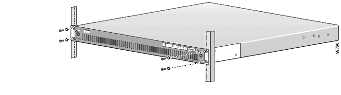
Figure 3-1 Attaching the Front of the Chassis to the Rack
Attaching the Rear Rack Extensions to the Chassis (Optional)
If the rear of the chassis is to be secured to the rack to provide additional support, then you must attach the left- and right-rear rack extensions (labeled Part #1 and Part #2, respectively) to the chassis before mounting the Cisco uMG9820 in the rack.
To attach rear rack extensions to the chassis:
Step 1
Caution
Step 2
a.
Tip
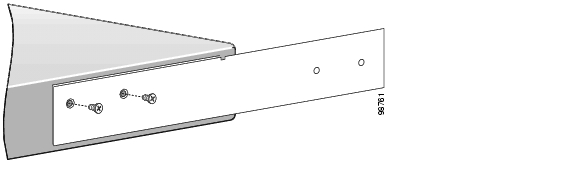
Figure 3-2 Attaching the Rear Rack Extension and Rear Rack-Mounting Brackets: Right-Side View
b.
Step 3
Tip
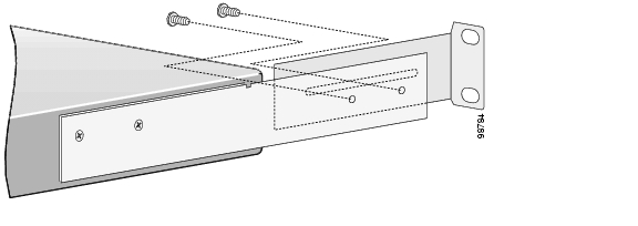
Figure 3-3 Attaching a Rear Rack-Mount Bracket to a Rear Rack Extension: Right-Side View
Step 4
Step 5
a.
b.
c.
Caution
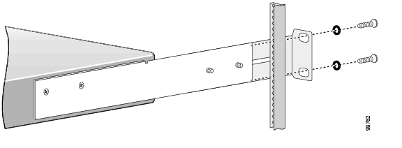
Figure 3-4 Attaching a Rear Rack-Mount Assembly to a Rear Rack Post: Right Side View
Step 6
Step 7
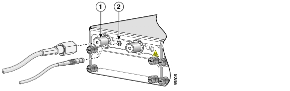
Connecting to QAM and RF Monitor Ports
This section describes how to connect cables to the QAM output and RF monitor ports with F-connectors and MCX connectors, respectively.
Caution
Note
To connect cables to QAM and RF monitor ports:
Step 1
Figure 3-5 Connecting Cables to QAM and RF Monitor Ports
Step 2
Step 3
Connecting to the Network
This section describes how to connect the Cisco uMG9820 to your network. The cables required to connect the gateway to a network are not provided. For ordering information, contact customer service (see Obtaining Additional Publications and Information, page xv).
Warning
Connecting the Gigabit Ethernet Ports
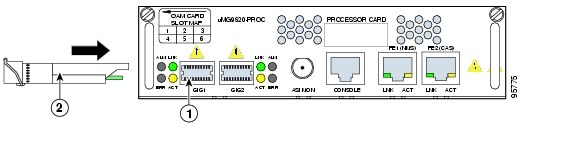
The Gigabit Ethernet ports support IEEE 802.3z specifications for 1000-Mbps transmission over fiber-optic cables. These ports also support autosensing and autonegotiation of the proper transmission mode (half duplex or full duplex) with an attached device. Cables connect to the GE ports by means of SFP (small form-factor pluggable) modules.
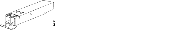
Installing SFP Modules
Each GE port requires an SFP module. See Figure 3-6. The following Warnings apply to fiber-optic SFPs.
Warning
Warning
Figure 3-6 Fiber-Optic SFP Module
Caution
Caution
To insert an SFP module into the SFP module slot:
Step 1
Caution
Step 2
Note
Step 3
Figure 3-7 Connecting the Gigabit Ethernet Port
Step 4
Caution
Step 5
Step 6
Note
Removing SFP Modules
To remove an SFP module:
Step 1
Step 2
Step 3
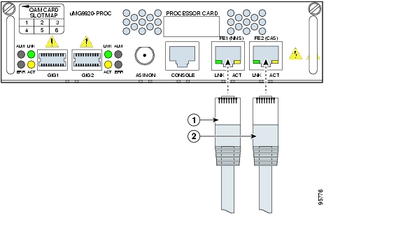
Connecting the Ethernet Ports to NMS and CAS Services
To support out-of-band management (Network Management System, or NMS) and conditional access system (CAS) traffic, the 10BASE-T/100BASE-TX Ethernet ports support IEEE 802.3 and IEEE 802.3u specifications for 10 Mbps and 100 Mbps transmission over unshielded twisted-pair (UTP) cables. These ports also support autosensing and autonegotiation of the proper transmission mode (half duplex or full duplex) with an attached device.
Note
Each Ethernet port has an RJ-45 connector that supports standard straight-through and crossover Category 5 UTP cable:
•
•
Note
To connect the Fast Ethernet ports to an Ethernet network in support of NMS and CAS services:
Step 1
Step 2
Step 3
Figure 3-8 Connecting the NMS and CAS Ports to the Network
Connecting to the Console Port
The Cisco uMG9820 is shipped with a console cable kit, which contains the cable and adapters you need to connect a console (an ASCII terminal or PC running terminal emulation software) to the Cisco uMG9820. The console cable kit includes the following:
•
•
Use the console terminal for local administrative access to the Cisco uMG9820. You can connect a terminal to the console port only.
To connect the console port to a terminal (an ASCII terminal or a PC running terminal emulation software):
Step 1
Step 2
Step 3
Note
9600 bits per second, 8 data bits, no parity, 1 stop bit
Connecting the Power
The Cisco uMG9820 features two AC power supplies that provide power factor correction and regulated outputs.
Warning
Warning
Caution
Before you start the Cisco uMG9820, ensure the following:
•
•
To connect the AC power to the Cisco uMG9820, use the following procedure:
Step 1
Step 2
Caution
![]()
![]()
![]()
![]()
![]()
![]()
![]()
![]()
Posted: Thu Oct 7 16:01:56 PDT 2004
All contents are Copyright © 1992--2004 Cisco Systems, Inc. All rights reserved.
Important Notices and Privacy Statement.