|
|

Table Of Contents
Information About Redundancy and Fail-Over
In-line Dual Link Redundant Topology
How to Configure Forced Failure
How to Force a Virtual Failure Condition
How to Exit a Virtual Failure Condition
Failure in the Cascade Connection
Replacing the SCE platform (manual recovery)
Reboot only (fully automatic recovery)
CLI Commands for Cascaded Systems
Topology-Related Parameters for Redundant Topologies
Configuring the Connection Mode
Firmware Upgrade (package installation)
Simultaneous Upgrade of Firmware and Application
Redundancy and Fail-Over
•
Information About Redundancy and Fail-Over
•
•
•
Information About Redundancy and Fail-Over
•
This module presents the fail-over and redundancy capabilities of the SCE platform. It first defines relevant terminology, as well as pertinent theoretical aspects of the redundancy and fail-over solution. It then explains specific recovery procedures for both single and dual link topologies. It also explains specific update procedures to be used in a cascaded SCE platform deployments. When fail over is required in a deployment, a topology with two cascaded SCE platforms is used. This cascaded solution provides both network link fail over, and fail over of the functionality of the SCE platform, including updated subscriber state.
Note
Terminology and Definitions
Following is a list of definitions of terms used in the chapter as they apply to the Cisco fail-over solution, which is based on cascaded SCE platforms.
•
•
•
•
Redundant Topologies
All Cisco SCE platforms include an internal electrical bypass module, which provide the capability of preserving the network link in case the SCE platform fails. The SCE platform, which can handle two data links, includes two such bypass modules. However, in some cases, the service provider wishes to preserve the SCE platform functionality in case of a failure, in addition to preserving the network link.
Cisco provides a unique solution for this scenario, through deploying two cascaded SCE platforms on these two data links.
The cascading is implemented by connecting the two SCE platforms using two of the data links. This fail over solution applies to both inline and receive-only topologies.
In each SCE platform, two of the four data interfaces are connected to each of the network links, while the other two data interfaces are used for cascading between the SCE platforms. (See the Cisco SCE 2000 Installation and Configuration Guide for specific cabling procedures for redundant topologies.) The cascade ports are used for transferring network traffic, keep-alive messages and subscriber state updates.
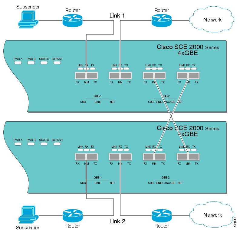
In-line Dual Link Redundant Topology
This topology serves inline deployments where the SCE platform functionality should be preserved in case of a failure, in addition to preserving the network link.
Figure 10-1 In-line Dual Link Redundant Topology
Failure Detection
The SCE platform has several types of mechanisms for detecting failures:
•
•
•
•
–
–
–
This type of failure, in most cases, does not require reboot of the SCE platform. When the connection with the SM is re-established the SCE platform is again ready for hot standby. If both SCE platforms lose their connections with the SM, it is assumed that it is the SM which has failed, thus, no action will be taken in the SCE platform.
Link Failure Reflection
The SCE platforms are transparent at Layers 2 and 3. The SCE platform operates in promiscuous mode, and the network elements on both sides of the SCE platform, are using the MAC address of the other network element when forwarding traffic.
To assist the network elements on both sides of the SCE platform to identify the link failures as quickly as possible, the SCE platform supports a functionality of reflecting to the other side of the SCE platforms events of link failure. When the link on one side of the SCE platform fails, the corresponding link on the other side is forced down, to reflect the failure. Link failure reflection is done on the traffic ports. When operating in deployments of single SCE platform with two data links, link failure is reflected between the two ports of each link.
When working with two cascaded SCE platforms, link failure is reflected in two cases:
•
•
Link failure reflection is supported both when the SCE platform is operational and when it is in failure/boot status.
Link reflection, like fail-over, is dependent on the bypass mechanism of the SCE platform
How to Configure Forced Failure
Use the following commands to force a virtual failure condition, and to exit from the failure condition when performing an application upgrade. (See How to Manage Application Files.)
•
•
How to Force a Virtual Failure Condition
Step 1
force failure-conditionand press Enter.Forces the SCE platform into a virtual failure state.
How to Exit a Virtual Failure Condition
Step 1
no force failure-conditionand press Enter.Exits from the virtual failure state.
Hot Standby and Fail-over
The fail over solution requires two SCE platforms connected in a cascade manner.
•
•
Hot Standby
In fail over solution, one of the SCE platforms is used as the active SCE platform and the other is used as the standby. Although traffic enters both the active and the standby SCE platforms, all traffic processing takes place in the SCE platform which is currently the active one. The active SCE platform processes the traffic coming on both links, its own link and the link connected to the standby SCE platform, as follows
•
•
Since only one SCE platform processes all traffic at any given time, split flows, which are caused by asymmetrical routing, that exist in the two data links are handled correctly.
To support subscriber-state fail-over, both SCE platforms hold subscriber states for all parties, and subscriber state updates are exchanged between the active SCE platform and the standby. This way, if the active SCE platform fails, the standby SCE platform is able to start serving the line immediately with a minimum loss of subscriber-state.
The two SCE platforms also use the cascade channel for exchanging periodic keep-alive messages.
Fail-over
In fail over solution, the two SCE platforms exchange keep alive messages via the cascade ports. This keep alive mechanism enables fast detection of failures between the SCE platforms and fast fail over to the standby SCE platform when required.
If the active SCE platform fails, the standby SCE platform then assumes the role of the active SCE platform.
The failed SCE platform uses its electrical bypass mechanism, which is a hardware entity that is separate from the main board and processors, to forward traffic to the other SCE platform, and to forward processed traffic back to the link. The previously standby SCE platform now processes all the traffic of this other link that is forwarded to it by the previously active SCE platform in addition to the traffic of its own link.
When the failed SCE platform recovers, it will remain in standby, while the previously standby SCE platform remains active. Switching the SCE platforms back to their original roles may be performed manually, if required, after the failed SCE platform has either recovered or been replaced.
If the failure is in the standby SCE platform, it will continue to forward traffic to the active SCE platform and back to its link, while the active SCE platform continues to provide its normal processing functionality to the traffic of the two links.
Note
There are two user-configurable options that are relevant in a situation when an SCE platform fails:
•
–
–
–
–
•
–
–
–
–
Failure in the Cascade Connection
The effect of a failure in the cascade connection between the two SCE platforms depends on whether one or both connections fail:
•
As long as one cascade connection remains up, the standby will cut off its traffic links so that all traffic is routed via the active SCE platform. Therefore, split flow is avoided, but at the expense of half line capacity.
•
Installing a Cascaded System
This section outlines the installation procedures for a redundant solution with two cascaded SCE platforms.
Refer to the Cisco SCE 2000 Installation and Configuration Guide for information on topologies and connections.
Refer to the Cisco Service Control Engine (SCE) CLI Command Reference for details of the CLI commands.
Note
SUMMARY STEPS
1.
2.
3.
4.
5.
6.
7.
8.
9.
10.
11.
DETAILED STEPS
Step 1
Step 2
Step 3
Step 4
Step 5
Step 6
Step 7
Step 8
Step 9
Step 10
Step 11
Recovery
•
•
This section specifies the procedure for recovery after a failure. The purpose of the recovery procedure is to restore the system to fully functional status. After the recovery procedure, the behavior of the system is the same as after installation.
A failed SCE platform may either recover automatically or be replaced (manual recovery). Whether recovery is automatic or manual depends on the original cause of the failure:
•
•
•
•
•
•
•
Replacing the SCE platform (manual recovery)
This is done in two stages, first manual installation steps performed by the technician, and then automatic configuration steps performed by the system.
•
Manual steps:
SUMMARY STEPS
1.
2.
3.
4.
5.
6.
DETAILED STEPS
Step 1
Step 2
Step 3
Step 4
Step 5
Step 6
Automatic steps (in parallel with the manual steps, requires no user intervention):
SUMMARY STEPS
1.
2.
3.
DETAILED STEPS
Step 1
Step 2
Step 3
Reboot only (fully automatic recovery)
SUMMARY STEPS
1.
2.
3.
4.
5.
6.
DETAILED STEPS
Step 1
Step 2
Step 3
Step 4
Step 5
Step 6
CLI Commands for Cascaded Systems
•
•
This section presents CLI commands relevant to the configuration and monitoring of a redundant system.
Use the following commands to configure and monitor a redundant system:
•
•
•
•
Topology-Related Parameters for Redundant Topologies
All four of the topology-related parameters are required when configuring a redundant topology.
•
–
–
•
•
•
Configuring the Connection Mode
Use the following command to configure the connection mode, including the following parameters.
•
•
•
•
To configure the connection mode, use the following command.
Step 1
Examples
EXAMPLE 1
Use the following command to configure the primary SCE platform in a two-SCE platform inline topology. Link 1 is connected to this SCE platform and the behavior of the SCE platform if a failure occurs is bypass .
SCE 2000(config if)#connection-mode inline-cascade physically-connected-links link-1
priority primary on-failure bypass
EXAMPLE 2
Use the following command to configure the SCE platform that might be cascaded with the SCE platform in Example 1. This SCE platform would have to be the secondary SCE platform, and Link 0 would be connected to this SCE platform, since Link 1 was connected to the primary. The connection mode would be the same as the first, and the behavior of the SCE platform if a failure occurs is also bypass.
SCE 2000(config if)# connection-mode inline-cascade physically-connected-links link-0
priority secondary on-failure bypass
How to Monitor the System
Use the following commands to view the current connection mode and link mode parameters.
•
•
•
How to View the Current Connection Mode
Step 1
show interface linecard 0 connection-modeand press Enter.How to View the Current Link Mode
Step 1
show interface linecard 0 link modeand press Enter.How to View Current Link Mappings
Step 1
show interface linecard 0 physically-connected-linksand press Enter.
System Upgrades
•
•
In a redundant solution, it is important that firmware and/or application upgrades be performed in such a way that line and service are preserved.
Refer to the following sections for instructions on how to perform these procedures on two cascaded SCE platforms:
•
•
•
Note
Firmware Upgrade (package installation)
SUMMARY STEPS
1.
2.
3.
4.
5.
6.
DETAILED STEPS
Step 1
Step 2
Step 3
Step 4
Step 5
Step 6
Application Upgrade
SUMMARY STEPS
1.
2.
3.
4.
5.
6.
7.
8.
DETAILED STEPS
Step 1
Step 2
Step 3
Step 4
Step 5
Step 6
Step 7
Step 8
Simultaneous Upgrade of Firmware and Application
SUMMARY STEPS
1.
2.
3.
4.
5.
6.
DETAILED STEPS
Step 1
a.
b.
c.
Step 2
This makes the updated SCE platform the active one, and it begins to give the NEW service.
Step 3
Since this includes a reboot, it is not necessary to undo the force failure command.
![]()
![]()
![]()
![]()
![]()
![]()
![]()
![]()
Posted: Wed May 30 08:53:51 PDT 2007
All contents are Copyright © 1992--2007 Cisco Systems, Inc. All rights reserved.
Important Notices and Privacy Statement.