Table Of Contents
Introduction to the SCE Platform
Information About The SCE Platform
Front Panel
Back Panel
Information About Checking the Shipping Container Contents
SCE 2000 Installation Checklist
Introduction to the SCE Platform
This chapter provides an introduction to the SCE 2000 4xGBE Platform, the Service Control hardware component.
• Information About The SCE Platform
Information About The SCE Platform
The Service Control Engine (SCE) platform, which is the hardware component of the Cisco Service Control solution, is designed to support observation, analysis, and control of Internet/IP traffic. The following table summarizes model information for the SCE 2000 platform
Table 2-1 SCE Platform Model Information
Model number
|
SCE 2020 4xGBE
|
Link Type
|
Gigabit Ethernet
|
Number of Ports
|
4
|
Number of Links
|
2
|
• Front Panel
• Back Panel
• Information About Checking the Shipping Container Contents
• SCE 2000 Installation Checklist
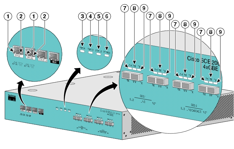
Front Panel
The SCE 2000 Front Panel consists of ports and LEDs as shown in the following figure and tables.
Figure 2-1 SCE 2000 Front Panel
Table 2-2 SCE 2000 Ports
Port
|
Quantity
|
Description
|
Connect This Port To...
|
Mng1/ Mng2
|
2
|
10/100/1000 Ethernet RJ-45 ports for management of the SCE 2000 .
CLI designation: interface Management 0/1, 0/2.
|
A LAN using an FE cable with an RJ-45 connector.
If both interfaces are used to provide a redundant management interface, connect both ports to the LAN via a switch.
|
Console
|
1
|
RS-232 RJ-45 port for use by technicians
|
A local terminal (console) using an RS-232 cable with an RJ-45 connector, as provided in the SCE 2000 kit.
|
AUX
|
1
|
RS-232 RJ-45 port used by technicians
|
|
GBE ports 1-4
|
4
|
GigabitEthernet ports for connecting to the line and/or cascading two devices
CLI designation: interface GigabitEthernet 0/1 through 0/4
|
|
Table 2-3 SCE 2000 LED Groups
LED Groups
|
Description
|
Power A
|
•Continuous green — Power supply A is functioning normally
•Red — Power supply A present, but malfunctioning
•Unlit — Power supply A is either not present or has failed.
|
Power B
|
•Continuous green — Power supply B is functioning normally
•Red — Power supply B present, but malfunctioning
•Unlit — Power supply B is either not present or has failed.
|
Status
|
The Status LED indicates the operational status of the SCE 2000 system, as follows:
•Unlit — indicates no power from either power unit.
•Orange — indicates that the system is booting up.
•Flashing green — indicates that the system is fully operational.
•Flashing orange — indicates that the system is operational, but is in a warning state.
•Red — indicates that there is a problem or failure
Note that Alarms are hierarchical: Failure takes precedence over Warning, which takes precedence over operational.
|
Bypass
|
•Continuous green — indicates that the traffic bypasses the SCE 2000 through an internal electrical bypass module.
Single SCE 2000 topology — The SCE 2000 is either in bypass or sniffing mode
Cascaded topology — Either the SCE 2000 is forwarding traffic to the other SCE 2000 , where it is being processed, or is simply in bypass mode, so traffic through it is not being processed.
•Unlit — traffic is not being bypassed
Single SCE 2000 topology — indicates normal operation of the SCE 2000
Cascaded topology — indicates normal operation of the active SCE 2000
|
GBE ports
|
The GBE LEDs indicate the operational status of the SCE 2000 line ports, as follows:
•Link
Green — indicates that the port link is up
Unlit — indicates that the port link is down
•Rx
Flashing Green — indicates that there are incoming packets
•Tx
Flashing Green — indicates that there are outgoing packets
|
Mng
|
The Mng port LEDs indicate the operational status of the SCE 2000 out-of-band LAN-based management port, as follows:
•Link/Active
Green — indicates that the port link is up
Unlit — indicates that the port link is down
•10/100/1000
Steady green — indicates that the port is set to 100 Mbps
Unlit — indicates that the port is set to 10 Mbps
Orange — indicates that the port is set to 1000 Mbps
|
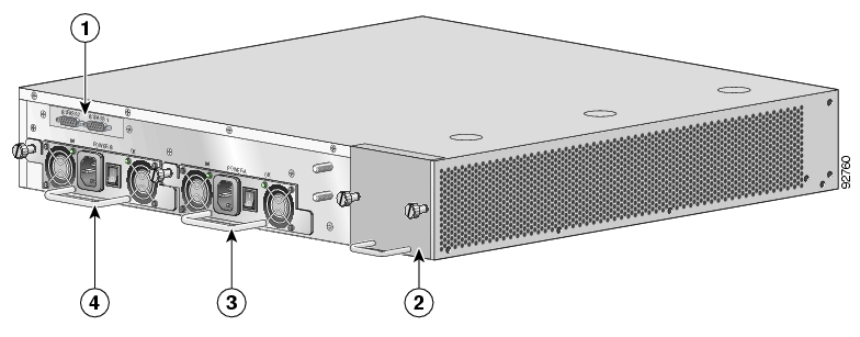
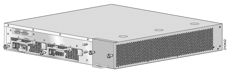
Back Panel
The SCE 2000 platform back-panel contains the following components:
•Two field-replaceable power supply units with ON/OFF switches
•A field-replaceable fan drawer
•Ground connections
•Two connectors to the external bypass module
The rear panels of both the AC- and DC-powered SCE 2000 platforms are shown in the following pair of figures.
Figure 2-2 SCE 2000 Back Panel: AC Power
Figure 2-3 SCE 2000 Back Panel: DC Power
Information About Checking the Shipping Container Contents
Use the SCE 2000 Component List to check the contents of the SCE 2000 platform shipping container.
Do not discard the shipping container. You need the container if you move or ship the SCE 2000 platform in the future.
• SCE 2000 Component List
SCE 2000 Component List
Table 2-4 SCE 2000 Component List
Component
|
Description
|
SCE 2000 platform
|
SCE 2020 4xGBE platform configured with either AC or DC power supplies.
|
Accessories
|
The following accessories might arrive in separate shipping containers:
|
Rack mount kit
|
•Two mounting brackets for 19" rack
•Six screws (Philips), 8-32 x 3/8" (for attaching the brackets to the SCE 2000 chassis)
•supporting mounting brackets for 19" rack
•Two crossrail supports for 19" rack with front and back posts
|
Management cables
|
•Fast Ethernet cable for connecting to the Management ports
•RS-232 serial cable (DB-9 to RJ-45) for connecting to a local terminal
|
Power cables
|
Two AC power supply cords,if ordered with AC-input power supply units
|
Grounding kit
|
•Grounding cable
•Two Hex nuts (#Φ")
•Two spring washers (#Φ")
|
Documentation
|
If ordered, SCE 2000 hardware and software documentation set and the Cisco Documentation CD-ROM package*
|
Optional Equipment
|
Four rubber feet for tabletop installation
|
External Optical Bypass module kit
|
•1 External Optical Bypass module
•1 19" rack mounting panel
•1 control cable
|
*Titles and quantities of documents will vary. You must order the type and quantity of documentation sets when you order the hardware.
Note We no longer ship the entire SCE 2000 documentation set automatically with each system. You must specifically order the documentation as part of the sales order. If you ordered documentation and did not receive it, we will ship the documents to you within 24 hours. To order documents, contact a customer service representative.
SCE 2000 Installation Checklist
To assist you with your installation and to provide a historical record of what was done by whom, photocopy the following SCE 2000 Installation Checklist. Indicate when each procedure or verification is completed. When the checklist is completed, place it in your site log along with the other records for your new SCE 2000 platform.
Table 2-5 SCE 2000 Installation Checklist
Task
|
Verified By
|
Date
|
Date SCE 2000 received
|
|
|
SCE 2000 and all accessories unpacked
|
|
|
Safety recommendations and guidelines reviewed
|
|
|
Topology verified: number of SCE 2000 platforms, number of links, and whether inline or receive-only
|
|
|
Installation Checklist copied
|
|
|
Site log established and background information entered
|
|
|
Site power voltages verified
|
|
|
Site environmental specifications verified
|
|
|
Required passwords, IP addresses, device names, and so on, needed for initial configuration available
|
|
|
Required tools available
|
|
|
Network connection equipment available
|
|
|
SCE 2000 mounted in rack (optional)
|
|
|
AC/DC power cables connected to AC/DC sources and SCE 2000 platform
|
|
|
Console port set for 9600 baud, 8 data bits, no parity, and 1 stop bit (9600 8N1)
|
|
|
ASCII terminal attached to console port
|
|
|
FE management ports are operational
|
|
|
GBE line and cascade ports operational
|
|
|
Network interface cables and devices connected
|
|
|
System power turned on
|
|
|
System boot complete (SYSTEM-UP LED is on)
|
|
|
Correct hardware configuration displayed after system banner appears
|
|
|