|
|

Table Of Contents
Hardware and Software Requirements and Restrictions (Catalyst 8540 MSR)
Hardware and Software Requirements and Restrictions (Catalyst 8510 MSR and LightStream 1010)
Configuring a Loopback Interface
Enabling Tag Switching on the ATM Interface
Configuring a VPI Range (Optional)
Configuring TDP Control Channels (Optional)
Configuring Tag Switching on VP Tunnels
Configuring the Service Class and Relative Weight
Displaying the TVC Configuration
Threshold Group for TBR Classes
Tag Switching Configuration Example
Configuring Tag Switching
This chapter describes tag switching, a high-performance packet-forwarding technology that assigns tags to mulitprotocol frames for transport across packet- or cell-based networks.
Note
This chapter provides advanced configuration instructions for the Catalyst 8540 MSR, Catalyst 8510 MSR, and LightStream 1010 ATM switch routers. For an overview of tag switching, refer to the Guide to ATM Technology. For complete descriptions of the commands mentioned in this chapter, refer to the ATM Switch Router Command Reference publication.
This chapter includes the following sections:
•
•
•
•
•
•
Tag Switching Overview
In conventional Layer 3 forwarding, as a packet traverses the network, each router extracts forwarding information from the Layer 3 header. Header analysis is repeated at each router (hop) through which the packet passes.
In a tag switching network, the Layer 3 header is analyzed just once. It is then mapped into a short fixed-length tag. At each hop, the forwarding decision is made by looking only at the value of the tag. There is no need to reanalyze the Layer 3 header. Because the tag is a fixed-length, unstructured value, lookup is fast and simple.
For an overview of how tag switching works and its benefits, refer to the Guide to ATM Technology.
Hardware and Software Requirements and Restrictions (Catalyst 8540 MSR)
The Catalyst 8540 MSR hardware requirements for tag switching include the following:
•
•
Tag switching has the following software restrictions:
•
•
•
Hardware and Software Requirements and Restrictions (Catalyst 8510 MSR and LightStream 1010)
The Catalyst 8510 MSR and LightStream 1010 ATM switch router hardware requirements for tag switching include the following:
•
•
•
Tag switching has the following software restrictions:
•
•
•
Configuring Tag Switching
This section describes how to configure tag switching on ATM switch routers, and includes the following procedures:
•
•
•
•
•
Configuring a Loopback Interface
You should configure a loopback interface on every ATM switch router configured for tag switching. The loopback interface, a virtual interface, is always active. The IP address of the loopback interface is used as the Tag Distribution Protocol (TDP) identifier for the ATM switch router. If a loopback interface does not exist, the TDP identifier is the highest IP address configured on the ATM switch router. If that IP address is administratively shut down, all TDP sessions through the ATM switch router restart. Therefore, we recommend that you configure a loopback interface.
To configure the loopback interface, perform the following steps, beginning in global configuration mode:
Step 1
Switch(config)# interface loopback number
Switch(config-if)#
Enters interface configuration mode and assigns a number to the loopback interface.
Step 2
Switch(config-if)# ip address ip-address mask
Assigns an IP address and subnet mask to the loopback interface.
Note
1 TVCs = tag virtual channels.
Example
In the following example, loopback interface 0 is created with an IP address of 1.0.1.11 and a subnet mask of 255.255.255.255:
Switch(config)# interface loopback 0Switch(config-if)# ip address 1.0.1.11 255.255.255.255Switch(config-if)# exitDisplaying Loopback Interface Configuration
The following example shows the loopback 0 configuration using the show interfaces privileged EXEC command:
Switch# show interfaces loopback 0Loopback0 is up, line protocol is upHardware is LoopbackInternet address is 1.0.1.11/24MTU 1500 bytes, BW 8000000 Kbit, DLY 5000 usec, rely 255/255, load 1/255Encapsulation LOOPBACK, loopback not set, keepalive set (10 sec)Last input 00:00:03, output never, output hang neverLast clearing of "show interface" counters neverQueueing strategy: fifoOutput queue 0/0, 0 drops; input queue 0/75, 0 drops5 minute input rate 0 bits/sec, 0 packets/sec5 minute output rate 0 bits/sec, 0 packets/sec0 packets input, 0 bytes, 0 no bufferReceived 0 broadcasts, 0 runts, 0 giants, 0 throttles0 input errors, 0 CRC, 0 frame, 0 overrun, 0 ignored, 0 abort73 packets output, 0 bytes, 0 underruns0 output errors, 0 collisions, 0 interface resets0 output buffer failures, 0 output buffers swapped outEnabling Tag Switching on the ATM Interface
Note
To enable tag switching on the ATM interface, perform the following steps, beginning in global configuration mode:
Examples
In the following example, ATM interface 1/0/1 is configured for IP unnumbered to loopback interface 0:
Switch(config-if)# interface atm 1/0/1Switch(config-if)# ip unnumbered loopback 0Switch(config-if)# tag-switching ipSwitch(config-if)# exitIn the following example, ATM interface 0/0/3 is configured with a specific IP address and subnet mask (1.3.11.3 255.255.0.0):
Switch(config)# interface atm 0/0/3Switch(config-if)# ip address 1.3.11.3 255.255.0.0Switch(config-if)# tag-switching ipSwitch(config-if)# exitDisplaying the ATM Interface Configuration
To display the ATM interface configuration, use the following EXEC command:
show tag-switching interfaces
Displays the tag switching configuration on the ATM interface.
The following example shows that tag switching is configured on ATM interfaces 0/0/3 and 1/0/1:
Switch# show tag-switching interfacesInterface IP Tunnel OperationalATM0/0/3 Yes No Yes (ATM tagging)ATM1/0/1 Yes No Yes (ATM tagging)Configuring OSPF
Enable OSPF on the ATM switch router so that it can create routing tables, which identify routes through the network. Then add the addresses and associated routing areas to the OSPF process so that it can propagate the addresses to other ATM switch routers:
Note
Example
The following is an example of OSPF enabled and assigned process number 10000. All addresses are in area 0:
Note
Switch(config)# router ospf 10000Switch(config-router)# network 1.1.1.0 0.0.0.255 area 0Switch(config-router)# network 1.2.1.0 0.0.0.255 area 0Switch(config-router)# network 1.3.0.0 0.0.255.255 area 0Switch(config-router)# network 200.2.2.0 0.0.0.255 area 0Switch(config-router)# network 1.0.1.0 0.0.0.255 area 0Switch(config-router)# network 1.18.0.0 0.0.255.255 area 0Displaying the OSPF Configuration
To display the OSPF configuration, use the following privileged EXEC command:
The following example shows the OSPF configuration using the show ip ospf privileged EXEC command:
Switch# show ip ospfRouting Process "ospf 10000" with ID 1.0.1.11Supports only single TOS(TOS0) routesSPF schedule delay 5 secs, Hold time between two SPFs 10 secsNumber of DCbitless external LSA 0Number of DoNotAge external LSA 0Number of areas in this router is 1. 1 normal 0 stub 0 nssaArea BACKBONE(0) (Inactive)Number of interfaces in this area is 4Area has no authenticationSPF algorithm executed 2 timesArea ranges areLink State Update Interval is 00:30:00 and due in 00:14:42Link State Age Interval is 00:20:00 and due in 00:14:10Number of DCbitless LSA 0Number of indication LSA 0Number of DoNotAge LSA 0Configuring a VPI Range (Optional)
Although not necessary for most configurations, you might need to change the default tag virtual path identifier (VPI) range on the switch if:
•
•
Note
To change the default tag VPI range, perform the following steps, beginning in global configuration mode:
Examples
The following example shows how to select a VPI range from 5 to 6 (a range of two), an acceptable range if the TDP neighbor is a router:
Switch(config)# interface atm 3/0/1Switch(config-if)# tag-switching ipSwitch(config-if)# tag-switching atm vpi 5 - 6The following example shows how to select a VPI range from 5 to 7 (a range of three), an acceptable range if the TDP neighbor is a switch:
Switch(config)# interface atm 3/0/1Switch(config-if)# tag-switching ipSwitch(config-if)# tag-switching atm vpi 5 - 7
Note
Displaying the Tag Switching VPI Range
To display the tag switching VPI range, use the following EXEC command:
show tag-switching interfaces detail
Displays the tag switching VPI range on an interface.
Example
The following example shows the tag switching VPI range on ATM interface 1/0/1:
Switch# show tag-switching interfaces detailInterface ATM0/0/3:IP tagging enabledTSP Tunnel tagging not enabledTagging operationalMTU = 4470ATM tagging: Tag VPI = 1, Control VC = 0/32Interface ATM1/0/1:IP tagging enabledTSP Tunnel tagging not enabledTagging operationalMTU = 4470ATM tagging: Tag VPI range = 5 - 6, Control VC = 6/32<information deleted>Configuring TDP Control Channels (Optional)
Although not necessary for most configurations, you can change the default Tag Distribution Protocol (TDP) control channel VPI and virtual channel identifier (VCI) if you want to use a nondefault value. The default TDP control channel is on VPI 0 and VCI 32. TDP control channels exchange TDP HELLOs and Protocol Information Elements (PIEs) to establish two-way TDP sessions. TVCs are created by the exchange of PIEs through TDP control channels.
To change the TDP control channel, perform the following steps, beginning in global configuration mode:
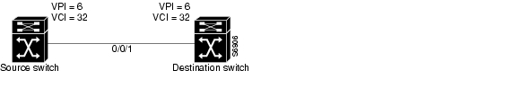
Figure 15-1 shows an example TDP control channel configuration between a source switch and destination switch on ATM interface 0/0/1. Note that the VPI and VCI values match on the source switch and destination switch.
Figure 15-1 Configuring TDP Control Channels
Examples
In the following example, a TDP control channel is configured on the source switch:
Switch(config)# interface atm 0/0/1Switch(config-if)# ip address 1.2.0.11 255.255.255.0Switch(config-if)# tag-switching ipSwitch(config-if)# tag-switching atm control-vc 6 32Switch(config-if)# exitIn the following example, a TDP control channel is configured on the destination switch:
Switch(config)# interface atm 0/0/1Switch(config-if)# ip address 1.2.0.12 255.255.255.0Switch(config-if)# tag-switching ipSwitch(config-if)# tag-switching atm control-vc 6 32Switch(config-if)# exitIf you are having trouble establishing a TDP session, verify that the VPI and VCI values match on the TDP control channels of the source switch and destination switch.
Displaying the TDP Control Channels
To display the TDP control channel configuration, use the following EXEC command:
show tag-switching interfaces detail
Displays the TDP control channel configuration on an interface.
The following example shows the TDP control channel configuration on interface ATM 0/0/3:
Switch# show tag-switching interfaces detailInterface ATM0/0/3:IP tagging enabledTSP Tunnel tagging not enabledTagging operationalMTU = 4470ATM tagging: Tag VPI = 1, Control VC = 0/32
<information deleted>Configuring Tag Switching on VP Tunnels
If you want to configure tag switching on virtual path (VP) tunnels, perform the following steps, beginning in global configuration mode:
Note
Because a VP tunnel runs between switches, you must also configure a VP tunnel on the connecting ATM interface on the destination switch. The examples that follow show how to configure VP tunnels between switches.
Note
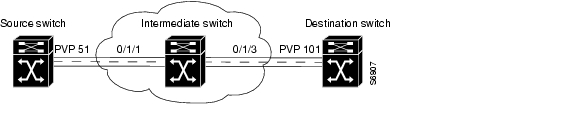
Figure 15-2 shows an example VP tunnel between a source switch and destination switch.
Figure 15-2 Configuring VP Tunnels
Examples
In the following example, ATM interface 0/1/1 on the source switch has no IP address and PVP 51 is configured for IP unnumbered to loopback interface 0:
Switch(config-if)# interface atm 0/1/1Switch(config-if)# atm pvp 51Switch(config-if)# exitSwitch(config-if)# interface atm 0/1/1.51Switch(config-subif)# ip unnumbered loopback 0Switch(config-subif)# tag-switching ipSwitch(config-subif)# exitIn the following example, ATM interface 0/1/3 on the destination switch has no IP address and PVP 101 is configured for IP unnumbered to loopback interface 0:
Switch(config)# interface atm 0/1/3Switch(config-if)# atm pvp 101Switch(config-if)# exitSwitch(config)# interface atm 0/1/3.101Switch(config-subif)# ip unnumbered loopback 0Switch(config-subif)# tag-switching ipSwitch(config-subif)# exitTo connect the source and destination switch VP tunnels, proceed to the next section, " Connecting the VP Tunnels."
Displaying the VP Tunnel Configuration
To display the VP tunnel configuration, use the following EXEC command:
The following example shows PVP 51 configured on ATM interface 0/1/1:
Switch# show atm vpInterface VPI Type X-Interface X-VPI StatusATM0/1/1 51 PVP TUNNELConnecting the VP Tunnels
To complete the VP tunnel, you must configure the ATM ports on the intermediate switch to designate where to send packets coming from the source switch and going to the destination switch.
To connect the permanent virtual path (PVP), perform the following steps, beginning in interface configuration mode:
Figure 15-3 shows an example configuration on an intermediate switch.
Figure 15-3 Connecting the VP Tunnels
Example
In the following example, PVP 51 on ATM interface 0/1/1 is connected to PVP 101 on ATM interface 0/1/3:
Switch(config)# interface atm 0/1/1Switch(config-if)# atm pvp 51 interface atm 0/1/3 101Switch(config-if)# exitDisplaying the VP Tunnel Configuration
The following example shows PVP 51 on ATM interface 0/1/1 connected to PVP 101 on ATM interface 0/1/3:
Switch# show atm vpInterface VPI Type X-Interface X-VPI StatusATM0/1/1 51 PVP ATM0/1/3 101 DOWNATM0/1/3 101 PVP ATM0/1/1 51 DOWNConfiguring VC Merge
VC merge allows the switch to aggregate multiple incoming flows with the same destination address into a single outgoing flow. Where VC merge occurs, several incoming tags are mapped to one single outgoing tag. Cells from different VCIs going to the same destination are transmitted to the same outgoing VC using multipoint-to-point connections. This sharing of tags reduces the total number of virtual circuits required for tag switching. Without VC merge, each source-destination prefix pair consumes one tag VC on each interface along the path. VC merge reduces the tag space shortage by sharing tags for different flows with the same destination.
Note
VC merge is enabled by default. To disable VC merge, enter the following command in global configuration mode:
Displaying the VC Merge Configuration
To display the VC merge configuration, use the following EXEC command:
show tag-switching atm-tdp capability
Displays the TDP control channel configuration on an interface.
The following example shows that VC merge configuration is enabled on ATM interface 0/1/0:
Switch# show tag-switching atm-tdp capabilityControl VPI VCI Alloc VC MergeATM0/1/0 VP VC Range Range Scheme IN OUTNegotiated 0 32 [7 - 8] [33 - 1023] UNIDIR - -Local - - [7 - 8] [33 - 16383] UNIDIR Yes YesPeer - - [7 - 8] [33 - 1023] UNIDIR - -Configuring Tag Switching CoS
Quality of service (QoS) allows ATM to meet the transmission quality and service availability of many different types of data. The need for delay-sensitive data, such as voice, can be given a higher priority than data that is not delay-sensitive, such as e-mail. The following service categories were created for ATM Forum VCs to meet the transmission needs of various types of data: VBR-RT, VBR-NRT, ABR, and UBR. Refer to Chapter 8, "Configuring Resource Management," for more information about the standard ATM Forum implementation of QoS. This section describes tag switching class of service (CoS).
Up to eight QoS classes (0 to 7) can be allocated to each physical interface port. Each port has an independent logical rate scheduler (RS) and a weighted round-robin (WRR) scheduler. The RS guarantees minimum bandwidth and has first priority on supplying an eligible cell for transmission. Second priority is given to the service classes, which have been assigned relative weights that are based on the ratio of the total leftover bandwidth. The service class relative weights are configurable so you can change the priority of the default values. The VCs within a service class also have relative weights. The service classes and VCs within a service class are scheduled by their relative weights.
With tag switching CoS, tag switching can dynamically set up to four tag virtual channels (TVCs) with different service categories between a source and destination. TVCs do not share the same QoS classes reserved for ATM Forum VCs (VBR-RT, VBR-NRT, ABR, and UBR). The following four new service classes were created for TVCs: TBR_1 (WRR_1), TBR_2 (WRR_2), TBR_3 (WRR_3), and TBR_4 (WRR_4). These new service classes are called Tag Bit Rate (TBR) classes. TVCs and ATM Forum VCs can only coexist on the same physical interface, but they operate in ships in the night (SIN) mode and are unaware of each other.
TBR classes support only best-effort VCs (similar to the ATM Forum service category UBR); therefore, there is no bandwidth guarantee from the RS, which is not used for TVCs. All of the TVCs fall into one of the four TBR classes, each carrying a different default relative weight. The default values of the relative weights for the four TBR classes are configurable, so you can change the priority of the default values.
Table 15-1 lists the TBR classes and ATM Forum class mappings into the service classes for physical ports.
Table 15-1 Service Class to Weight Mapping for Physical Ports
TBR_1 (WRR_1)
1
1
TBR_2 (WRR_2)
6
2
TBR_3 (WRR_3)
7
3
TBR_4 (WRR_4)
8
4
CBR1
2
8
VBR-RT
2
8
VBR-NRT
3
1
ABR
4
1
UBR
5
1
1 Even though the CBR service category is mapped to service class 2, all of the CBR VCs are rate scheduled only, and therefore they are not WRR scheduled.
When tag switching is enabled on a hierarchical VP tunnel, the tunnel can only be used for tag switching. Because hierarchical VP tunnels support only four service classes, both TVCs and ATM Forum VCs map to the same service classes. Therefore, both ATM Forum VCs and TVCs cannot coexist in a hierarchical VP tunnel. The relative weights assigned to the service classes depend on which is active (either tag switching or ATM Forum). The class weights change whenever a hierarchical VP tunnel is toggled between ATM Forum and tag switching. By default, a hierarchical VP tunnel comes up as an ATM Forum port.
Table 15-2 lists the TBR classes and ATM Forum service category mappings for hierarchical VP tunnels.
Table 15-2 Service Class to Weight Mapping for Hierarchical VP Tunnels
TBR_1 (WRR_1)
1
1
TBR_2 (WRR_2)
2
2
TBR_3 (WRR_3)
3
3
TBR_4 (WRR_4)
4
4
Configuring the Service Class and Relative Weight
Each service class is assigned a relative weight. These weights are configurable and range from 1 to 15.
To configure the service class and relative weight on a specific interface, perform the following steps, beginning in global configuration mode:
Example
In the following example, ATM interface 0/0/3 is configured with service class 1 and a WRR weight of 3:
Switch(config)# interface atm 0/0/3Switch(config-if)# atm service-class 1 wrr-weight 3Displaying the TVC Configuration
To display the TVC configuration, perform the following task in EXEC mode:
show atm vc interface atm card/subcard/port [vpi vci]
Displays the ATM layer connection information about the virtual connection.
The following example shows the service category of the TVC:
Switch# show atm vc interface atm 0/0/3 1 35Interface: ATM0/0/3, Type: oc3suniVPI = 1 VCI = 35Status: UPTime-since-last-status-change: 1d00hConnection-type: TVC(I)Cast-type: multipoint-to-point-inputPacket-discard-option: enabledUsage-Parameter-Control (UPC): passWrr weight: 2Number of OAM-configured connections: 0OAM-configuration: disabledOAM-states: Not-applicableCross-connect-interface: ATM0/1/3.10, Type: oc3suniCross-connect-VPI = 10Cross-connect-VCI = 34Cross-connect-UPC: passCross-connect OAM-configuration: disabledCross-connect OAM-state: Not-applicableThreshold Group: 7, Cells queued: 0Rx cells: 0, Tx cells: 0Tx Clp0:0, Tx Clp1: 0Rx Clp0:0, Rx Clp1: 0Rx Upc Violations:0, Rx cell drops:0Rx pkts:0, Rx pkt drops:0Rx connection-traffic-table-index: 63998Rx pcr-clp01: noneRx scr-clp01: noneRx mcr-clp01: noneRx cdvt: 1616833580 (from default for interface)Rx mbs: noneTx connection-traffic-table-index: 63998Tx pcr-clp01: noneTx scr-clp01: noneTx mcr-clp01: noneTx cdvt: noneTx mbs: noneThreshold Group for TBR Classes
A threshold group utilizes the memory efficiently among VCs of a particular traffic type. Each threshold group is programmed with a dynamic memory allocation profile that maps into the needs of the connections of a particular service class. There are 16 threshold groups (0 to 15) available on the ATM switch router. Each threshold group has a set of eight regions, and each region has a set of thresholds. When these thresholds are exceeded, cells are dropped to maintain the integrity of the shared memory resource.
Each ATM Forum service category is mapped into a distinct threshold group. All the connections in a particular service category map into one threshold group. Similarly, all the Tag Bit Rate (TBR) classes have best effort traffic and the service differentiation comes mainly by giving different weights. Each of the TBR classes map into four different threshold groups whose parameters are the same as the unspecified bit rate (UBR) threshold group.
Table 15-3 shows the threshold group parameters mapped to the connections in all of the TBR classes for the Catalyst 8540 MSR.
Table 15-4 shows the threshold group parameters mapped to the connections in all of the TBR classes for the Catalyst 8510 MSR and LightStream 1010 ATM switch routers.
Each threshold group is divided into eight regions. Each region has a set of thresholds that are calculated from the corresponding threshold group parameters given in Table 15-3. The threshold group might be in any one of the regions depending on the fill level (cell occupancy) of that group. And that region is used to derive the set of thresholds which apply to all the connections in that group.
Table 15-5 gives the eight thresholds for threshold groups 6, 7, 8, and 9.
For more information about threshold groups and configuration parameters, refer to the "Overview of Threshold Groups" section on page 8-15 and the Guide to ATM Technology.
CTT Row
A row in the connection traffic table (CTT) is created for each unique combination of traffic parameters. When a TVC is set up in response to a request by tag switching, a CTT row is obtained from the resource manager by passing the traffic parameters that include the service category (TBR_x [WRR_x], where x is 1, 2, 3, or 4). If a match is found for the same set of traffic parameters, the row index is returned; otherwise a new table is created and the row index of that CTT row is returned. Since all data TVCs use the same traffic parameters, the same CTT row can be used for all TVCs of a particular service category once it is created.
Note
RM CAC Support
Connection admission control (CAC) is not supported for tag virtual channels (TVCs). All TVCs are best effort connections; therefore, no bandwidth is guaranteed by the RS. Only the WRR scheduler is used. So, all of the traffic parameters (PCR, MCR, MBS, CDVT, and SCR) are unspecified. There is no best effort limit like there is with ATM Forum UBR and ABR connections. CAC is bypassed for TVCs.
Tag Switching Configuration Example
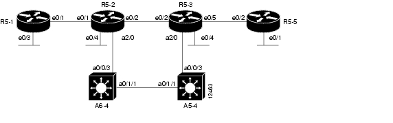
Figure 15-4 shows an example tag switching network.
Figure 15-4 Example Network for Tag Switching
Router 5-1 Configuration
The configuration of router R5-1, interface e0/1, follows:
router_R5-1#configure terminalrouter_R5-2(config)# ip cef switchrouter_R5-1(config)#tag-switching advertise-tagsrouter_R5-1(config)#interface e0/1router_R5-1(config-if)#tag-switching iprouter_R5-1(config-if)#exitrouter_R5-1(config)#Router 5-2 Configuration
The configuration between router R5-1, interface e0/1, and R5-2, interface e0/1, follows:
router_R5-2# configure terminalrouter_R5-2(config)# ip cef switchrouter_R5-2(config)# tag-switching advertise-tagsrouter_R5-2(config)# interface e0/1router_R5-2(config-if)# tag-switching iprouter_R5-2(config-if)# exitrouter_R5-2(config)#The configuration between router R5-2, interface e0/2, and R5-3, interface e0/2, follows:
route_R5-2(config)# interface e0/2route_R5-2(config-if)# tag-switching iproute_R5-2(config-if)# exitThe configuration of router R5-2, interface a2/0.1, follows:
router_R5-2(config-if)# interface a2/0.1router_R5-2(config-subif)# ip address 189.26.11.15 255.255.0.0router_R5-2(config-subif)# tag-switching iprouter_R5-2(config-subif)# no shutdownrouter_R5-2(config-subif)# exitrouter_R5-2(config)# interface a2/0router_R5-2(config)# no shutdownRouter 5-3 Configuration
The configuration of router R5-3, interface e0/2, follows:
router_R5-3#configure terminalrouter_R5-3(config)#ip cef switchrouter_R5-3(config)#tag-switching advertise-tagsrouter_R5-3(config)#interface e0/2router_R5-3(config-if)#tag-switching iprouter_R5-3(config-if)#exitThe configuration of router R5-3, interface e0/5 follows:
router_R5-3(config)# interface e0/5router_R5-3(config-if)# tag-switching iprouter_R5-3(config-if)# exitThe configuration of router R5-3, interface atm 2/0.1, follows:
router_R5-3# configure terminalrouter_R5-3(config)# interface atm 2/0.1router_R5-3(config-if)# ip address 189.25.12.13 255.255.0.0router_R5-3(config-if)# tag-switching iprouter_R5-3(config-if)# no shutdownrouter_R5-3(config-if)# exitrouter_R5-3(config)# interface a2/0router_R5-3(config-if)# no shutdownATM Switch Router A5-4 Configuration
The configuration of ATM switch router A5-4, interfaces atm 0/1/1 and atm 0/0/3, follows:
atm_A5-4# configure terminalatm_A5-4(config)# interface atm 0/1/1atm_A5-4(config-if)# no shutdownatm_A5-4(config-if)# ip address 189.24.15.12 255.255.0.0atm_A5-4(config-if)# tag-switching ipatm_A5-4(config-if)# exitatm_A5-4(config)# tag-switching ipatm_A5-4(config)# interface atm 0/0/3atm_A5-4(config-if)# no shutdownatm_A5-4(config-if)# ip address 189.25.15.11 255.255.0.0atm_A5-4(config-if)# tag-switching ipatm_A5-4(config-if)# exitatm_A5-4(config)# tag-switching ipRouter 5-5 Configuration
The configuration of router R5-5, interface e0/2, follows:
router_R5-5# configure terminalrouter_R5-5(config)# ip cef switchrouter_R5-5(config)# tag-switching advertise-tagsrouter_R5-5(config)# interface e0/2router_R5-5(config-if)# tag-switching iprouter_R5-5(config-if)# exitATM Switch Router A6-4 Configuration
The configuration of ATM switch router A6-4, interface atm 0/1/1, follows:
atm_A6-4# configure terminalatm_A6-4(config)# interface atm 0/1/1atm_A6-4(config-if)# no shutdownatm_A6-4(config-if)# ip address 189.24.14.12 255.255.0.0atm_A6-4(config-if)# tag-switching ipatm_A6-4(config-if)# exitThe configuration of ATM switch router A6-4, interface atm 0/0/3, follows:
atm_A6-4# configure terminalatm_A6-4(config)# interface atm 0/0/3atm_A6-4(config-if)# no shutdownatm_A6-4(config-if)# ip address 189.26.14.11 255.255.0.0atm_A6-4(config-if)# tag-switching ipatm_A6-4(config-if)# exit
![]()
![]()
![]()
![]()
![]()
![]()
![]()
![]()
Posted: Mon Oct 11 09:26:30 PDT 2004
All contents are Copyright © 1992--2004 Cisco Systems, Inc. All rights reserved.
Important Notices and Privacy Statement.