|
|

Table Of Contents
Configuring ATM Routing and PNNI
Configuring ATM Address Groups
Configuring PNNI without Hierarchy
Configuring the Lowest Level of the PNNI Hierarchy
Configuring Higher Levels of the PNNI Hierarchy
Configuring ATM PNNI Statistics Collection
Configuring ATM Routing and PNNI
This chapter describes the Interim Interswitch Signaling Protocol (IISP) and Private Network-Network Interface (PNNI) ATM routing protocol implementations on the ATM switch router.
Note
This chapter provides advanced configuration instructions for the Catalyst 8540 MSR, Catalyst 8510 MSR, and LightStream 1010 ATM switch routers. For further information about IISP and PNNI, refer to the Guide to ATM Technology. For complete descriptions of the commands mentioned in this chapter, refer to the ATM Switch Router Command Reference publication.
This chapter includes the following sections:
•
Overview
To place calls between ATM end systems, signalling consults either IISP, a static routing protocol, or PNNI, a dynamic routing protocol. PNNI provides quality of service (QoS) routes to signalling based on the QoS requirements specified in the call setup request.
For detailed discussions of the following topics, refer to the Guide to ATM Technology:
•
•
•
ATM Addresses
The autoconfigured ATM address of the ATM switch router suffices when implementing single-level PNNI. Hierarchical PNNI requires an addressing scheme to ensure global uniqueness of the ATM address and to plan for future network expansion.
For detailed discussions of the following related topics, refer to the Guide to ATM Technology:
•
•
•
•
Configuring PNNI 2.0 E.164 AESA Prefix Encoding Support
The ATM switch router supports automatic PNNI 2.0 encoding of E.164 AESA prefixes. To configure automatic PNNI 2.0 encoding, use the following ATM router configuration command:
aesa embedded-number left-justified
Enables automatic conversion of E.164 AESA prefixes into left-justified encoding format.
The aesa embedded-number left-justified command causes the conversion of all reachable address prefixes with the E.164 Authority and Format Identifier (AFI), including reachable address prefixes advertised by remote PNNI nodes, routes learned by ILMI, and reachable address prefixes installed by the switch router automatically. This affects the atm route, auto-summary, summary-address, show atm route, and show atm pnni summary commands. The atm address, atm prefix, and show atm addresses commands are not affected because they do not use PNNI address prefixes.
Note
Example
The following example shows how to configure the switch router to convert the E.164 AESA prefixes to PNNI 2.0 format, beginning in global configuration mode:
Switch# configure terminalSwitch(config)# atm router pnniSwitch(config-atm-router)# aesa embedded-number left-justifiedDisplaying the PNNI 2.0 E.164 AESA Prefix Encoding Support Configuration
To display the PNNI 2.0 E.164 AESA prefix encoding support configuration, use the following EXEC command:
show atm pnni aesa embedded-number
Displays the configuration of the automatic conversion of E.164 AESA prefixes into left-justified encoding format.
Example
The following example show how to display the configuration of the automatic conversion of E.164 AESA prefixes into left-justified encoding format:
Switch# show atm pnni aesa embedded-numberAESA embedded-number is left-justified.IISP Configuration
This section describes the procedures necessary for Interim Interswitch Signaling Protocol (IISP) configuration, and includes the following subsections:
•
Configuring the Routing Mode
The ATM routing software can be restricted to operate in static mode. In this mode, the call routing is restricted to only the static configuration of ATM routes, disabling operation of any dynamic ATM routing protocols, such as PNNI.
The atm routing-mode command is different from deleting all PNNI nodes using the node command and affects Integrated Local Management Interface (ILMI) autoconfiguration. If the switch is configured using static routing mode on each interface, the switch ILMI variable atmfAtmLayerNniSigVersion is set to IISP. This causes either of the following to happen:
•
•
Note
To configure the routing mode, perform these steps, beginning in global configuration mode:
Example
The following example shows how to use the atm routing-mode static command to restrict the switch operation to static routing mode:
Switch(config)# atm routing-mode staticThis Configuration Will Not Take Effect Until Next Reload.Switch(config)# endSwitch# copy system:running-config nvram:startup-configBuilding configuration...[OK]Switch# reloadThe following example shows how to reset the switch operation back to PNNI if the switch is operating in static mode:
Switch(config)# no atm routing-mode staticThis Configuration Will Not Take Effect Until Next Reload.Switch(config)# endSwitch# copy system:running-config nvram:startup-configBuilding configuration...[OK]Switch# reloadDisplaying the ATM Routing Mode Configuration
To display the ATM routing mode configuration, use the following privileged EXEC command:
Example
The following example shows the ATM routing mode configuration using the more system:running-config privileged EXEC command:
Switch# more system:running-configBuilding configuration...Current configuration:!version 11.2<information deleted>!hostname Switch!username dtateip rcmd remote-username dplatz!atm e164 translation-tablee164 address 1111111 nsap-address 11.111111111111111111111111.112233445566.11e164 address 2222222 nsap-address 22.222222222222222222222222.112233445566.22e164 address 3333333 nsap-address 33.333333333333333333333333.112233445566.33!atm routing-mode static
atm address 47.0091.8100.0000.0040.0b0a.2b81.0040.0b0a.2b81.00!<information deleted>Configuring the ATM Address
If you are planning to implement only a flat topology network (and have no future plans to migrate to PNNI hierarchy), you can skip this section and use the preconfigured ATM address assigned by Cisco Systems.
Note
To change the active ATM address, create a new address, verify that it exists, and then delete the current active address. Follow these steps, beginning in global configuration mode:
Example
The following example shows how to add the ATM address prefix 47.0091.8100.5670.000.0ca7.ce01. Using the ellipses (...) adds the default Media Access Control (MAC) address as the last six bytes.
Switch(config)# atm address 47.0091.8100.5670.0000.0ca7.ce01...Switch(config)# no atm address 47.0091.8100.0000.0041.0b0a.1081...Displaying the ATM Address Configuration
To display the ATM address configuration, use the following EXEC command:
Example
The following example shows the ATM address configuration using the show atm addresses EXEC command:
Switch# show atm addressesSwitch Address(es):47.00918100567000000CA7CE01.00410B0A1081.00Soft VC Address(es):47.0091.8100.0000.0041.0b0a.1081.4000.0c80.0000.00 ATM0/0/047.0091.8100.0000.0041.0b0a.1081.4000.0c80.0000.63 ATM0/0/0.9947.0091.8100.0000.0041.0b0a.1081.4000.0c80.0010.00 ATM0/0/147.0091.8100.0000.0041.0b0a.1081.4000.0c80.0020.00 ATM0/0/247.0091.8100.0000.0041.0b0a.1081.4000.0c80.0030.00 ATM0/0/347.0091.8100.0000.0041.0b0a.1081.4000.0c80.1000.00 ATM0/1/047.0091.8100.0000.0041.0b0a.1081.4000.0c80.1010.00 ATM0/1/147.0091.8100.0000.0041.0b0a.1081.4000.0c80.1020.00 ATM0/1/247.0091.8100.0000.0041.0b0a.1081.4000.0c80.1030.00 ATM0/1/347.0091.8100.0000.0041.0b0a.1081.4000.0c80.8000.00 ATM1/0/047.0091.8100.0000.0041.0b0a.1081.4000.0c80.8010.00 ATM1/0/147.0091.8100.0000.0041.0b0a.1081.4000.0c80.8020.00 ATM1/0/247.0091.8100.0000.0041.0b0a.1081.4000.0c80.8030.00 ATM1/0/347.0091.8100.0000.0041.0b0a.1081.4000.0c80.9000.00 ATM1/1/047.0091.8100.0000.0041.0b0a.1081.4000.0c80.9010.00 ATM1/1/147.0091.8100.0000.0041.0b0a.1081.4000.0c80.9020.00 ATM1/1/247.0091.8100.0000.0041.0b0a.1081.4000.0c80.9030.00 ATM1/1/3ILMI Switch Prefix(es):47.0091.8100.0000.0041.0b0a.108147.0091.8100.0000.0060.3e5a.db01ILMI Configured Interface Prefix(es):LECS Address(es):Configuring Static Routes
Use the atm route command to configure a static route. A static route attached to an interface allows all ATM addresses matching the configured address prefix to be reached through that interface.
Note
To configure a static route, use the following global configuration command:
Examples
The following example uses the atm route command to configure a static route to the 13-byte switch prefix 47.00918100000000410B0A1081 to ATM interface 0/0/0:
Switch(config)# atm route 47.0091.8100.0000.0041.0B0A.1081 atm 0/0/0The following example uses the atm route command to configure a static route to the 13-byte switch prefix 47.00918100000000410B0A1081 to ATM interface 0/0/0 configured with a scope 1 associated:
Switch(config)# atm route 47.0091.8100.0000.0041.0B0A.1081 atm 0/0/0 scope 1Displaying the Static Route Configuration
To display the ATM static route configuration, use the following EXEC command:
Examples
The following example shows the ATM static route configuration using the show atm route privileged EXEC command:
Switch# show atm routeCodes: P - installing Protocol (S - Static, P - PNNI, R - Routing control),T - Type (I - Internal prefix, E - Exterior prefix, SE -Summary Exterior prefix, SI - Summary Internal prefix,ZE - Suppress Summary Exterior, ZI - Suppress Summary Internal)P T Node/Port St Lev Prefix~ ~~ ~~~~~~~~~~~~~~~~ ~~ ~~~ ~~~~~~~~~~~~~~~~~~~~~~~~~~~~~~~~~~~~~~~~~~~~~~~~~~~S E 1 ATM0/0/0 DN 56 47.0091.8100.0000/56S E 1 ATM0/0/0 DN 0 47.0091.8100.0000.00/64(E164 Address 1234567)R SI 1 0 UP 0 47.0091.8100.0000.0041.0b0a.1081/104R I 1 ATM0 UP 0 47.0091.8100.0000.0041.0b0a.1081.0041.0b0a.1081/152R I 1 ATM0 UP 0 47.0091.8100.0000.0041.0b0a.1081.4000.0c/128R SI 1 0 UP 0 47.0091.8100.5670.0000.0000.0000/104R I 1 ATM0 UP 0 47.0091.8100.5670.0000.0000.0000.0040.0b0a.1081/152R I 1 ATM0 UP 0 47.0091.8100.5670.0000.0000.0000.4000.0c/128Configuring ATM Address Groups
ATM address groups allow more than one interface to have the same internal address prefix for the same static route. These multiple static routes provide load balancing for traffic from an end station.
Configure the interfaces in a group by performing the following tasks, beginning in global configuration mode:
Example
The following example shows how to configure ATM interface 1/1/0 and ATM interface 3/0/1 in ATM address group 5:
Switch(config)# interface atm 1/1/0Switch(config-if)# atm interface-group 5Switch(config-if)# exitSwitch(config)# interface atm 3/0/1Switch(config-if)# atm interface-group 5Displaying ATM Address Group Configuration
To determine if an interface is a member of an ATM address group, use the following privileged EXEC command:
show running-config interface atm card/subcard/port
Shows the ILMI configuration on a per-port basis.
Example
The following example shows the ATM address group configuration for ATM interface 1/1/0 and ATM interface 3/0/1:
Switch# show running-config interface atm 1/1/0Building configuration...Current configuration:!no ip addressno ip directed-broadcastno atm ilmi-keepaliveatm prefix 47.0091.8100.5670.0000.0000.1122...clock source free-runningendSwitch# show running-config interface atm 3/0/1Building configuration...Current configuration:!no ip addressno ip directed-broadcastno atm ilmi-keepaliveatm prefix 47.0091.8100.5670.0000.0000.1122...clock source free-runningendBasic PNNI Configuration
This section describes all the procedures necessary for a basic PNNI configuration and includes the following subsections:
•
•
•
Configuring PNNI without Hierarchy
The ATM switch router defaults to a working PNNI configuration suitable for operation in isolated flat topology ATM networks. The switch comes with a globally unique preconfigured ATM address. Manual configuration is not required if you:
•
•
•
If you plan to migrate your flat network topology to a PNNI hierarchical topology, proceed to the next section "Configuring the Lowest Level of the PNNI Hierarchy."
Configuring the Lowest Level of the PNNI Hierarchy
This section describes how to configure the lowest level of the PNNI hierarchy. The lowest-level nodes comprise the lowest level of the PNNI hierarchy. When only the lowest-level nodes are configured, there is no hierarchical structure. If your network is relatively small and you want the benefits of PNNI, but do not need the benefits of a hierarchical structure, follow the procedures in this section to configure the lowest level of the PNNI hierarchy.
To implement multiple levels of PNNI hierarchy, first complete the procedures in this section and then proceed to the "Configuring Higher Levels of the PNNI Hierarchy" section .
Configuring an ATM Address and PNNI Node Level
The ATM switch router is preconfigured as a single lowest-level PNNI node (locally identified as node 1) with a level of 56. The node ID and peer group ID are calculated based on the current active ATM address.
Note
To configure a node in a higher level of the PNNI hierarchy, the value of the node level must be a smaller number. For example, a three-level hierarchical network could progress from level 72 to level 64 to level 56. Notice that the level numbers graduate from largest at the lowest level (72) to smallest at the highest level (56).
To change the active ATM address you must create a new address, verify that it exists, and then delete the current active address. After you have entered the new ATM address, disable node 1 and then reenable it. At the same time, you can change the node level if required for your configuration. The identifiers for all higher level nodes are recalculated based on the new ATM address.
Caution
To change the active ATM address, perform these steps, beginning in global configuration mode:
Example
The following example changes the ATM address of the switch from the autoconfigured address 47.0091.8100.0000.0041.0b0a.1081.0041.0b0a.1081.00 to the new address prefix 47.0091.8100.5670.0000.0000.1122.0041.0b0a.1081.00, and causes the node identifier and peer group identifier to be recalculated:
Switch(config)# atm address 47.0091.8100.5670.0000.0000.1122...Switch(config)# no atm address 47.0091.8100.0000.0041.0b0a.1081...Switch(config)# atm router pnniSwitch(config-atm-router)# node 1 disableSwitch(config-pnni-node)# node 1 enableDisplaying the PNNI Node Configuration
To display the ATM PNNI node configuration, use the following privileged EXEC command:
Example
The following example shows the PNNI node configuration using the show atm pnni local-node privileged EXEC command:
Switch# show atm pnni local-nodePNNI node 1 is enabled and runningNode name: eng_1System address 47.0091810000000002EB1FFE00.0002EB1FFE00.01Node ID 56:160:47.0091810000000002EB1FFE00.0002EB1FFE00.00Peer group ID 56:160:47.0000.0000.0000.0000.0000Level 56, Priority 0 0, No. of interfaces 1, No. of neighbors 0Parent Node Index: 2Node Allows Transit CallsNode Representation: simpleHello interval 15 sec, inactivity factor 5,Hello hold-down 10 tenths of secAck-delay 10 tenths of sec, retransmit interval 5 sec,Resource poll interval 5 secSVCC integrity times: calling 35 sec, called 50 sec,Horizontal Link inactivity time 120 sec,PTSE refresh interval 1800 sec, lifetime factor 200 percent,Min PTSE interval 10 tenths of secAuto summarization: on, Supported PNNI versions: newest 1, oldest 1Default administrative weight mode: uniformMax admin weight percentage: -1Next resource poll in 3 secondsMax PTSEs requested per PTSE request packet: 32Redistributing static routes: YesConfiguring Static Routes
Because PNNI is a dynamic routing protocol, static routes are not necessary between nodes that support PNNI. However, you can extend the routing capability of PNNI beyond nodes that support PNNI to:
•
•
Use the atm route command to configure a static route. A static route attached to an interface allows all ATM addresses matching the configured address prefix to be reached through that interface.
Note
To configure a static route connection, use the following global configuration command:
atm route addr-prefix atm card/subcard/port [e164-address address-string [number-type numtype]] [internal] [scope org-scope]
Specifies a static route to a reachable address prefix.
Examples
The following example uses the atm route command to configure a static route to the 13-byte switch prefix 47.00918100000000410B0A1081 to ATM interface 0/0/0:
Switch(config)# atm route 47.0091.8100.0000.0041.0B0A.1081 atm 0/0/0The following example uses the atm route command to configure a static route to the 13-byte switch prefix 47.00918100000000410B0A1081 to ATM interface 0/0/0 configured with a scope 1 associated:
Switch(config)# atm route 47.0091.8100.0000.0041.0B0A.1081 atm 0/0/0 scope 1Displaying the Static Route Configuration
To display the ATM static route configuration, use the following EXEC command:
Example
The following example shows the ATM static route configuration using the show atm route EXEC command:
Switch# show atm routeCodes: P - installing Protocol (S - Static, P - PNNI, R - Routing control),T - Type (I - Internal prefix, E - Exterior prefix, SE -Summary Exterior prefix, SI - Summary Internal prefix,ZE - Suppress Summary Exterior, ZI - Suppress Summary Internal)P T Node/Port St Lev Prefix~ ~~ ~~~~~~~~~~~~~~~~ ~~ ~~~ ~~~~~~~~~~~~~~~~~~~~~~~~~~~~~~~~~~~~~~~~~~~~~~~~~~~S E 1 ATM0/0/0 DN 56 47.0091.8100.0000/56S E 1 ATM0/0/0 DN 0 47.0091.8100.0000.00/64(E164 Address 1234567)R SI 1 0 UP 0 47.0091.8100.0000.0041.0b0a.1081/104R I 1 ATM0 UP 0 47.0091.8100.0000.0041.0b0a.1081.0041.0b0a.1081/152R I 1 ATM0 UP 0 47.0091.8100.0000.0041.0b0a.1081.4000.0c/128R SI 1 0 UP 0 47.0091.8100.5670.0000.0000.0000/104R I 1 ATM0 UP 0 47.0091.8100.5670.0000.0000.0000.0040.0b0a.1081/152R I 1 ATM0 UP 0 47.0091.8100.5670.0000.0000.0000.4000.0c/128Configuring a Summary Address
You can configure summary addresses to reduce the amount of information advertised by a PNNI node and contribute to scalability in large networks. Each summary address consists of a single reachable address prefix that represents a collection of end system or node addresses. We recommend that you use summary addresses when all end system addresses that match the summary address are directly reachable from the node. However, this is not always required because routes are always selected by nodes advertising the longest matching prefix to a destination address.
By default, each lowest-level node has a summary address equal to the 13-byte address prefix of the ATM address of the switch. This address prefix is advertised into its peer group.
You can configure multiple addresses for a single switch which are used during ATM address migration. ILMI registers end systems with multiple prefixes during this period until an old address is removed. PNNI automatically creates 13-byte summary address prefixes from all of its ATM addresses.
You must configure summary addresses (other than the defaults) on each node. Each node can have multiple summary address prefixes. Use the summary-address command to manually configure summary address prefixes.
Note
To configure a summary address, perform these steps, beginning in global configuration mode:
Example
The following example shows how to remove the default summary address(es) and add summary address 47.009181005670:
Switch(config)# atm router pnniSwitch(config-atm-router)# node 1Switch(config-pnni-node)# no auto-summarySwitch(config-pnni-node)# summary-address 47.009181005670Displaying the Summary Address Configuration
To display the ATM PNNI summary address configuration, use the following privileged EXEC command:
Example
The following example shows the ATM PNNI summary address configuration using the show atm pnni summary privileged EXEC command:
Switch# show atm pnni summaryCodes: Node - Node index advertising this summaryType - Summary type (INT - internal, EXT - exterior)Sup - Suppressed flag (Y - Yes, N - No)Auto - Auto Summary flag (Y - Yes, N - No)Adv - Advertised flag (Y - Yes, N - No)Node Type Sup Auto Adv Summary Prefix~~~~ ~~~~ ~~~ ~~~~ ~~~ ~~~~~~~~~~~~~~~~~~~~~~~~~~~~~~~~~~~~~~~~~~~~~~~~~~~1 Int N Y Y 47.0091.8100.0000.0040.0b0a.2a81/1042 Int N Y N 47.01b1.0000.0000.0000.00/80Configuring Scope Mapping
The PNNI address scope allows you to restrict advertised reachability information within configurable boundaries.
Note
In PNNI networks, the scope is specified in terms of PNNI levels. The mapping from organizational scope values used at UNI and IISP interfaces to PNNI levels is configured on the lowest-level node. The mapping can be determined automatically (which is the default setting) or manually, depending on the configuration of the scope mode command.
In manual mode, whenever the level of node 1 is modified, the scope map should be reconfigured to avoid unintended suppression of reachability advertisements. Misconfiguration of the scope map might cause addresses to remain unadvertised.
In automatic mode, the UNI to PNNI level mapping is automatically reconfigured whenever the level of the node 1 is modified. The automatic reconfiguration avoids misconfigurations caused by node level modifications. Automatic adjustment of scope mapping uses the values shown in Table 10-1.
Entering the scope mode automatic command ensures that all organizational scope values cover an area at least as wide as the current node's peer group. Configuring the scope mode to manual disables this feature and no changes can be made without explicit configuration.
To configure the PNNI scope mapping, perform these steps, beginning in global configuration mode:
Step 1
Switch(config)# atm router pnni
Switch(config-atm-router)#
Enters ATM router PNNI mode.
Step 2
Switch(config-atm-router)# node node-index
Switch(config-pnni-node)#
Enters node configuration mode.
Step 3
Switch(config-pnni-node)# scope mode manual
Configures scope mode as manual.1
Step 4
Switch(config-pnni-node)# scope map low-org-scope [high-org-scope] level number
Configures node scope mapping.
1 You must enter the scope mode manual command to allow scope mapping configuration.
Example
The following example shows how to configure PNNI scope mapping manually so that organizational scope values 1 through 8 map to PNNI level 72:
Switch(config)# atm router pnniSwitch(config-atm-router)# node 1Switch(config-pnni-node)# scope mode manualSwitch(config-pnni-node)# scope map 1 8 level 72Displaying the Scope Mapping Configuration
To display the PNNI scope mapping configuration, use the following privileged EXEC command:
Example
The following example shows the ATM PNNI scope mapping configuration using the show atm pnni scope privileged EXEC command:
Switch# show atm pnni scopeUNI scope PNNI Level~~~~~~~~~ ~~~~~~~~~~(1 - 10) 56(11 - 12) 48(13 - 14) 32(15 - 15) 0Scope mode: manualConfiguring Higher Levels of the PNNI Hierarchy
Once you have configured the lowest level of the PNNI hierarchy, you can configure the higher levels. To do so, you must configure peer group leaders (PGLs) and logical group nodes (LGNs).
For an explanation of PGLs and LGNs, as well as guidelines for creating a PNNI hierarchy, refer to the Guide to ATM Technology.
Configuring a Logical Group Node and Peer Group Identifier
The LGN is created only when the child node in the same switch (that is, the node whose parent configuration points to this node) is elected PGL of the child peer group.
The peer group identifier defaults to a value created from the first part of the child peer group identifier, and does not need to be specified. If you want a nondefault peer group identifier, you must configure all logical nodes within a peer group with the same peer group identifier.
Higher level nodes are only active if:
•
•
To configure a LGN and peer group identifier, perform these steps, beginning in global configuration mode:
Examples
The following example shows how to create a new node 2 with a level of 56 and a peer group identifier of 56:47009111223344:
Switch(config)# atm router pnniSwitch(config-atm-router)# node 2 level 56 peer-group-identifier 56:47009111223344 enableSwitch(config-pnni-node)# endNotice that the PNNI level and the first two digits of the peer group identifier are the same.
Displaying the Logical Group Node Configuration
To display the LGN configuration, use the following privileged EXEC command:
Example
The following example shows the PNNI node information using the show atm pnni local-node privileged EXEC command:
Switch# show atm pnni local-node 2PNNI node 2 is enabled and not runningNode name: Switch.2.56System address 47.009181000000000000000001.000000000001.02Node ID 56:0:00.000000000000000000000000.000000000001.00Peer group ID 56:47.0091.1122.3344.0000.0000.0000Level 56, Priority 0 0, No. of interfaces 0, No. of neighbors 0Parent Node Index: NONENode Allows Transit CallsNode Representation: simpleHello interval 15 sec, inactivity factor 5,Hello hold-down 10 tenths of secAck-delay 10 tenths of sec, retransmit interval 5 sec,Resource poll interval 5 secSVCC integrity times: calling 35 sec, called 50 sec,Horizontal Link inactivity time 120 sec,PTSE refresh interval 1800 sec, lifetime factor 200 percent,Min PTSE interval 10 tenths of secAuto summarization: on, Supported PNNI versions: newest 1, oldest 1Default administrative weight mode: uniformMax admin weight percentage: -1Max PTSEs requested per PTSE request packet: 32Redistributing static routes: NoConfiguring the Node Name
PNNI node names default to names based on the host name. However, you can change the default node name to more accurately reflect the peer group. We recommend you chose a node name of 12 characters or less so that your screen displays remain nicely formatted and easy to read.
After a node name has been configured, it is distributed to all other nodes by PNNI flooding. This allows the node to be identified by its node name in PNNI show commands.
Note
To configure the PNNI node name, perform these steps, beginning in global configuration mode:
Example
Configure the name of the node as eng_1 using the name command, as in the following example:
Switch(config)# atm router pnniSwitch(config-atm-router)# node 1Switch(config-pnni-node)# name eng_1Displaying the Node Name Configuration
To display the ATM PNNI node name configuration, use the following privileged EXEC command:
Example
This example shows how to display the ATM node name configuration using the show atm pnni local-node command from user EXEC mode:
Switch# show atm pnni local-nodePNNI node 1 is enabled and runningSystem address 47.0091810000000002EB1FFE00.0002EB1FFE00.01Node ID 56:160:47.0091810000000002EB1FFE00.0002EB1FFE00.00Peer group ID 56:16.0347.0000.0000.0000.0000.0000Level 56, Priority 0 0, No. of interfaces 1, No. of neighbors 0Parent Node Index: 2Node Allows Transit CallsNode Representation: simpleHello interval 15 sec, inactivity factor 5,Hello hold-down 10 tenths of secAck-delay 10 tenths of sec, retransmit interval 5 sec,Resource poll interval 5 secSVCC integrity times: calling 35 sec, called 50 sec,Horizontal Link inactivity time 120 sec,PTSE refresh interval 1800 sec, lifetime factor 200 percent,Min PTSE interval 10 tenths of secAuto summarization: on, Supported PNNI versions: newest 1, oldest 1Default administrative weight mode: uniformMax admin weight percentage: -1Next resource poll in 3 secondsMax PTSEs requested per PTSE request packet: 32Redistributing static routes: YesConfiguring a Parent Node
For a node to be eligible to become a PGL within its own peer group, you must configure a parent node and a nonzero election leadership level (described in the following section, " Configuring the Node Election Leadership Priority"). If the node is elected a PGL, the node specified by the parent command becomes the parent node and represents the peer group at the next hierarchical level.
To configure a parent node, perform these steps, beginning in global configuration mode:
Example
The following example shows how to create a parent node for node 1:
Switch(config)# atm router pnniSwitch(config-pnni-node)# node 1Switch(config-pnni-node)# parent 2Displaying the Parent Node Configuration
To display the parent node configuration, use the following privileged EXEC command:
Example
The following example shows the ATM parent node information using the show atm pnni hierarchy privileged EXEC command:
Switch# show atm pnni hierarchyLocally configured parent nodes:Node ParentIndex Level Index Local-node Status Node Name~~~~~ ~~~~~ ~~~~~~ ~~~~~~~~~~~~~~~~~~~~ ~~~~~~~~~~~~~~~~~~~~~~1 80 2 Enabled/ Running Switch2 72 N/A Enabled/ Running Switch.2.72Configuring the Node Election Leadership Priority
Normally the node with the highest election leadership priority is elected PGL. If two nodes share the same election priority, the node with the highest node identifier becomes the PGL. To be eligible for election the configured priority must be greater than zero. You can configure multiple nodes in a peer group with nonzero leadership priority so that if one PGL becomes unreachable, the node configured with the next highest election leadership priority becomes the new PGL.
Note
The control for election is done through the assignment of leadership priorities. We recommend that the leadership priority space be divided into three tiers:
•
•
•
This subdivision is used because when a node becomes PGL, it increases the advertised leadership priority by a value of 50. This avoids instabilities after election.
The following guidelines apply when configuring the node election leadership priority:
•
•
•
•
Note
To configure the election leadership priority, perform these steps, beginning in global configuration mode:
Example
The following example shows how to change the election leadership priority for node 1 to 100:
Switch(config)# atm router pnniSwitch(config-pnni-node)# node 1Switch(config-pnni-node)# election leadership-priority 100Displaying Node Election Leadership Priority
To display the node election leadership priority, use one of the following privileged EXEC commands:
show atm pnni election
Displays the node election leadership priority.
show atm pnni election peers
Displays all nodes in the peer group.
Examples
The following example shows the election leadership priority using the show atm pnni election privileged EXEC command:
Switch# show atm pnni electionPGL Status.............: PGLPreferred PGL..........: (1) SwitchPreferred PGL Priority.: 255Active PGL.............: (1) SwitchActive PGL Priority....: 255Active PGL For.........: 00:01:07Current FSM State......: PGLE Operating: PGLLast FSM State.........: PGLE Awaiting UnanimityLast FSM Event.........: Unanimous VoteConfigured Priority....: 205Advertised Priority....: 255Conf. Parent Node Index: 2PGL Init Interval......: 15 secsSearch Peer Interval...: 75 secsRe-election Interval...: 15 secsOverride Delay.........: 30 secsThe following example shows all nodes in the peer group using the show atm pnni election peers command:
Switch# show atm pnni election peersNode No. Priority Connected Preferred PGL~~~~~~~~ ~~~~~~~~ ~~~~~~~~~ ~~~~~~~~~~~~~1 255 Yes Switch9 0 Yes Switch10 0 Yes Switch11 0 Yes Switch12 0 Yes SwitchConfiguring a Summary Address
Summary addresses can be used to decrease the amount of information advertised by a PNNI node. Summary addresses should only be used when all end system addresses that match the summary address are directly reachable from this node. However, this is not always required because routes are always selected to nodes advertising the longest matching prefix to a destination address.
A single default summary address is configured for each logical group node (LGN) in the PNNI hierarchy. The length of that summary for any LGN equals the level of the child peer group, and its value is equal to the first level bits of the child peer group identifier. This address prefix is advertised into the LGN's peer group.
Summary addresses other than defaults must be explicitly configured on each node. A node can have multiple summary address prefixes. Note also that every node in a peer group that has a potential to become a peer group leader (PGL) should have the same summary address lists in its parent node configuration.
Note
To configure the ATM PNNI summary address prefix, perform these steps, beginning in global configuration mode:
Example
The following example shows how to remove the default summary address(es) and add summary address 47.009181005670:
Switch(config)# atm router pnniSwitch(config-atm-router)# node 1Switch(config-pnni-node)# no auto-summarySwitch(config-pnni-node)# summary-address 47.009181005670Displaying the Summary Address Configuration
To display the ATM PNNI summary address configuration, use the following privileged EXEC command:
Example
The following example shows the ATM PNNI summary address configuration using the show atm pnni summary privileged EXEC command:
Switch# show atm pnni summaryCodes: Node - Node index advertising this summaryType - Summary type (INT - internal, EXT - exterior)Sup - Suppressed flag (Y - Yes, N - No)Auto - Auto Summary flag (Y - Yes, N - No)Adv - Advertised flag (Y - Yes, N - No)Node Type Sup Auto Adv Summary Prefix~~~~ ~~~~ ~~~ ~~~~ ~~~ ~~~~~~~~~~~~~~~~~~~~~~~~~~~~~~~~~~~~~~~~~~~~~~~~~~~1 Int N Y Y 47.0091.8100.0000.0040.0b0a.2a81/1042 Int N Y N 47.01b1.0000.0000.0000.00/80PNNI Hierarchy Configuration Example
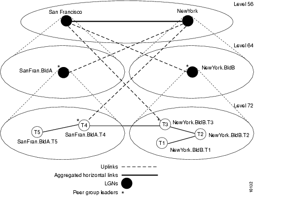
An example configuration for a three-level hierarchical topology is shown in Figure 10-1. The example shows the configuration of only five switches, although there can be many other switches in each peer group.
Figure 10-1 Example Three-Level Hierarchical Topology
At the lowest level (level 72), the hierarchy represents two separate peer groups. Each of the four switches named T2 to T5 are eligible to become a peer group leader (PGL) at two levels, and each has two configured ancestor nodes (a parent node or a parent node's parent). Switch T1 has no configured ancestor nodes and is not eligible to become a PGL. As a result of the peer group leader election at the lowest level, switches T4 and T3 become leaders of their peer groups. Therefore, each switch creates an LGN at the second level (level 64) of the hierarchy. As a result of the election at the second level of the hierarchy, logical group nodes (LGNs) SanFran.BldA and NewYork.BldB are elected as PGLs, creating LGNs at the highest level of the hierarchy (level 56). At that level, the uplinks that have been induced through level 64 form an aggregated horizontal link within the common peer group at level 56.
Examples
The sections that follow show the configurations for each switch and the outputs of the show atm pnni local-node command. Some of the output text has been suppressed because it is not relevant to the example.
Switch NewYork.BldB.T1 Configuration
hostname NewYork.BldB.T1atm address 47.0091.4455.6677.1144.1011.1233.0060.3e7b.3a01.00atm router pnninode 1 level 72 lowestredistribute atm-staticNewYork.BldB.T1# show atm pnni local-nodePNNI node 1 is enabled and runningNode name: NewYork.BldB.T1System address 47.009144556677114410111233.00603E7B3A01.01Node ID 72:160:47.009144556677114410111233.00603E7B3A01.00Peer group ID 72:47.0091.4455.6677.1144.0000.0000Level 72, Priority 0 0, No. of interfaces 3, No. of neighbors 2Parent Node Index: NONE<information deleted>Switch NewYork.BldB.T2 Configuration
hostname NewYork.BldB.T2atm address 47.0091.4455.6677.1144.1011.1244.0060.3e5b.bc01.00atm router pnninode 1 level 72 lowestparent 2redistribute atm-staticelection leadership-priority 40node 2 level 64parent 3election leadership-priority 40name NewYork.BldBnode 3 level 56name NewYorkNewYork.BldB.T2# show atm pnni local-nodePNNI node 1 is enabled and runningNode name: NewYork.BldB.T2System address 47.009144556677114410111244.00603E5BBC01.01Node ID 72:160:47.009144556677114410111244.00603E5BBC01.00Peer group ID 72:47.0091.4455.6677.1144.0000.0000Level 72, Priority 40 40, No. of interfaces 3, No. of neighbors 1Parent Node Index: 2<information deleted>PNNI node 2 is enabled and not runningNode name: NewYork.BldBSystem address 47.009144556677114410111244.00603E5BBC01.02Node ID 64:72:47.009144556677114400000000.00603E5BBC01.00Peer group ID 64:47.0091.4455.6677.1100.0000.0000Level 64, Priority 40 40, No. of interfaces 0, No. of neighbors 0Parent Node Index: 3<information deleted>PNNI node 3 is enabled and not runningNode name: NewYorkSystem address 47.009144556677114410111244.00603E5BBC01.03Node ID 56:64:47.009144556677110000000000.00603E5BBC01.00Peer group ID 56:47.0091.4455.6677.0000.0000.0000Level 56, Priority 0 0, No. of interfaces 0, No. of neighbors 0Parent Node Index: NONE<information deleted>Switch NewYork.BldB.T3 Configuration
hostname NewYork.BldB.T3atm address 47.0091.4455.6677.1144.1011.1255.0060.3e5b.c401.00atm router pnninode 1 level 72 lowestparent 2redistribute atm-staticelection leadership-priority 45node 2 level 64parent 3election leadership-priority 45name NewYork.BldBnode 3 level 56name NewYorkNewYork.BldB.T3# show atm pnni local-nodePNNI node 1 is enabled and runningNode name: NewYork.BldB.T3System address 47.009144556677114410111255.00603E5BC401.01Node ID 72:160:47.009144556677114410111255.00603E5BC401.00Peer group ID 72:47.0091.4455.6677.1144.0000.0000Level 72, Priority 45 95, No. of interfaces 4, No. of neighbors 1Parent Node Index: 2<information deleted>PNNI node 2 is enabled and runningNode name: NewYork.BldBSystem address 47.009144556677114410111255.00603E5BC401.02Node ID 64:72:47.009144556677114400000000.00603E5BC401.00Peer group ID 64:47.0091.4455.6677.1100.0000.0000Level 64, Priority 45 95, No. of interfaces 0, No. of neighbors 0Parent Node Index: 3<information deleted>PNNI node 3 is enabled and runningNode name: NewYorkSystem address 47.009144556677114410111255.00603E5BC401.03Node ID 56:64:47.009144556677110000000000.00603E5BC401.00Peer group ID 56:47.0091.4455.6677.0000.0000.0000Level 56, Priority 0 0, No. of interfaces 0, No. of neighbors 1Parent Node Index: NONE<information deleted>Switch SanFran.BldA.T4 Configuration
hostname SanFran.BldA.T4atm address 47.0091.4455.6677.2233.1011.1266.0060.3e7b.2001.00atm router pnninode 1 level 72 lowestparent 2redistribute atm-staticelection leadership-priority 45node 2 level 64parent 3election leadership-priority 45name SanFran.BldAnode 3 level 56name SanFranSanFran.BldA.T4# show atm pnni local-nodePNNI node 1 is enabled and runningNode name: SanFran.BldA.T4System address 47.009144556677223310111266.00603E7B2001.01Node ID 72:160:47.009144556677223310111266.00603E7B2001.00Peer group ID 72:47.0091.4455.6677.2233.0000.0000Level 72, Priority 45 95, No. of interfaces 4, No. of neighbors 1Parent Node Index: 2<information deleted>PNNI node 2 is enabled and runningNode name: SanFran.BldASystem address 47.009144556677223310111266.00603E7B2001.02Node ID 64:72:47.009144556677223300000000.00603E7B2001.00Peer group ID 64:47.0091.4455.6677.2200.0000.0000Level 64, Priority 45 95, No. of interfaces 0, No. of neighbors 0Parent Node Index: 3<information deleted>PNNI node 3 is enabled and runningNode name: SanFranSystem address 47.009144556677223310111266.00603E7B2001.03Node ID 56:64:47.009144556677220000000000.00603E7B2001.00Peer group ID 56:47.0091.4455.6677.0000.0000.0000Level 56, Priority 0 0, No. of interfaces 0, No. of neighbors 1Parent Node Index: NONE<information deleted>Switch SanFran.BldA.T5 Configuration
hostname SanFran.BldA.T5atm address 47.0091.4455.6677.2233.1011.1244.0060.3e7b.2401.00atm router pnninode 1 level 72 lowestparent 2redistribute atm-staticelection leadership-priority 10node 2 level 64parent 3election leadership-priority 40name SanFran.BldAnode 3 level 56name SanFranSanFran.BldA.T5# show atm pnni local-nodePNNI node 1 is enabled and runningNode name: SanFran.BldA.T5System address 47.009144556677223310111244.00603E7B2401.01Node ID 72:160:47.009144556677223310111244.00603E7B2401.00Peer group ID 72:47.0091.4455.6677.2233.0000.0000Level 72, Priority 10 10, No. of interfaces 2, No. of neighbors 1Parent Node Index: 2<information deleted>PNNI node 2 is enabled and not runningNode name: SanFran.BldASystem address 47.009144556677223310111244.00603E7B2401.02Node ID 64:72:47.009144556677223300000000.00603E7B2401.00Peer group ID 64:47.0091.4455.6677.2200.0000.0000Level 64, Priority 40 40, No. of interfaces 0, No. of neighbors 0Parent Node Index: 3<information deleted>PNNI node 3 is enabled and not runningNode name: SanFranSystem address 47.009144556677223310111244.00603E7B2401.03Node ID 56:64:47.009144556677220000000000.00603E7B2401.00Peer group ID 56:47.0091.4455.6677.0000.0000.0000Level 56, Priority 0 0, No. of interfaces 0, No. of neighbors 0Parent Node Index: NONE<information deleted>Advanced PNNI Configuration
This section describes how to configure advanced PNNI features. The advanced features described in this section are not required to enable PNNI, but are provided to tune your network performance.
For additional information about the features described in this section, refer to the Guide to ATM Technology.
This section includes the following subsections:
•
Tuning Route Selection
The tasks described in the following subsections are used to tune the mechanisms by which routes are selected in your PNNI network.
Configuring Background Route Computation
The ATM switch router supports the following two route selection modes:
•
•
The background routes mode should be enabled in large networks where it usually exhibits less stringent processing requirements and better scalability. Route computation is performed at almost every poll interval when a significant change in the topology of the network is reported or when significant threshold changes have occurred since the last route computation.
To configure the background route computation, perform these steps, beginning in global configuration mode:
Example
The following example shows how to enable background routes and configures the background routes poll interval to 30 seconds:
Switch(config)# atm router pnniSwitch(config-atm-router)# background-routes-enable poll-interval 30Displaying the Background Route Computation Configuration
To display the background route configuration, use the following privileged EXEC commands:
show atm pnni background status
Displays the background route configuration.
show atm pnni background routes
Displays background routing tables.
Examples
The following example shows the ATM PNNI background route configuration using the show atm pnni background status privileged EXEC command:
Switch# show atm pnni background statusBackground Route Computation is EnabledBackground Interval is set at 10 secondsBackground Insignificant Threshold is set at 32The following example shows the ATM PNNI background route tables for constant bit rate (CBR) using the show atm pnni background routes privileged EXEC command:
Switch# show atm pnni background routes cbrBackground Routes From CBR/AW Table~~~~~~~~~~~~~~~~~~~~~~~~~~~~~~~~~~~~~~2 Routes To Node 21. Hops 1. 1:ATM0/1/2 -> 2->: aw 5040 cdv 138 ctd 154 acr 147743 clr0 10 clr01 10<-: aw 5040 cdv 138 ctd 154 acr 147743 clr0 10 clr01 102. Hops 1. 1:ATM0/1/1 -> 2->: aw 5040 cdv 138 ctd 154 acr 147743 clr0 10 clr01 10<-: aw 5040 cdv 138 ctd 154 acr 147743 clr0 10 clr01 101 Routes To Node 51. Hops 1. 1:ATM0/1/0 -> 5->: aw 5040 cdv 138 ctd 154 acr 147743 clr0 10 clr01 10<-: aw 5040 cdv 138 ctd 154 acr 147743 clr0 10 clr01 10Background Routes From CBR/CDV Table~~~~~~~~~~~~~~~~~~~~~~~~~~~~~~~~~~~~~~2 Routes To Node 21. Hops 1. 1:ATM0/1/2 -> 2->: aw 5040 cdv 138 ctd 154 acr 147743 clr0 10 clr01 10<-: aw 5040 cdv 138 ctd 154 acr 147743 clr0 10 clr01 102. Hops 1. 1:ATM0/1/1 -> 2->: aw 5040 cdv 138 ctd 154 acr 147743 clr0 10 clr01 10<-: aw 5040 cdv 138 ctd 154 acr 147743 clr0 10 clr01 101 Routes To Node 51. Hops 1. 1:ATM0/1/0 -> 5->: aw 5040 cdv 138 ctd 154 acr 147743 clr0 10 clr01 10<-: aw 5040 cdv 138 ctd 154 acr 147743 clr0 10 clr01 10Background Routes From CBR/CTD Table~~~~~~~~~~~~~~~~~~~~~~~~~~~~~~~~~~~~~~2 Routes To Node 21. Hops 1. 1:ATM0/1/2 -> 2->: aw 5040 cdv 138 ctd 154 acr 147743 clr0 10 clr01 10<-: aw 5040 cdv 138 ctd 154 acr 147743 clr0 10 clr01 102. Hops 1. 1:ATM0/1/1 -> 2->: aw 5040 cdv 138 ctd 154 acr 147743 clr0 10 clr01 10<-: aw 5040 cdv 138 ctd 154 acr 147743 clr0 10 clr01 101 Routes To Node 51. Hops 1. 1:ATM0/1/0 -> 5->: aw 5040 cdv 138 ctd 154 acr 147743 clr0 10 clr01 10<-: aw 5040 cdv 138 ctd 154 acr 147743 clr0 10 clr01 10Background Routes From CBR/CTD Table~~~~~~~~~~~~~~~~~~~~~~~~~~~~~~~~~~~~~~2 Routes To Node 21. Hops 1. 1:ATM0/1/2 -> 2->: aw 5040 cdv 138 ctd 154 acr 147743 clr0 10 clr01 10<-: aw 5040 cdv 138 ctd 154 acr 147743 clr0 10 clr01 102. Hops 1. 1:ATM0/1/1 -> 2->: aw 5040 cdv 138 ctd 154 acr 147743 clr0 10 clr01 10<-: aw 5040 cdv 138 ctd 154 acr 147743 clr0 10 clr01 101 Routes To Node 51. Hops 1. 1:ATM0/1/0 -> 5->: aw 5040 cdv 138 ctd 154 acr 147743 clr0 10 clr01 10<-: aw 5040 cdv 138 ctd 154 acr 147743 clr0 10 clr01 10Configuring Link Selection
Link selection applies to parallel PNNI links between two switches. Link selection allows you to choose the method the switch uses during call setup for selecting one link among multiple parallel links to forward the call.
Note
Table 10-2 lists the PNNI link selection methods from which you can choose.
1 CBR = constant bit rate
2 VBR-RT = variable bit rate real time
3 VBR-NRT = variable bit rate non-real time
4 ABR = available bit rate
5 UBR = unspecified bit rate
The switch applies a single link selection method for a group of parallel links connected to a neighbor switch. If multiple links within this group are configured with a different link selection method, then the switch selects a method according to the order of precedence as shown in Table 10-2.
The link selection feature allows you to specify one or more links among the parallel links as an alternate (or backup) link. An alternate link is a link that is used only when all other non-alternate links are either down or full. Alternate links are not considered part of the parallel link group targeted for link selection. Calls are always load balanced over multiple parallel alternate links by default.
To configure the PNNI link selection feature, perform these steps, beginning in global configuration mode:
Examples
The following example shows how to configure link selection on ATM interface 0/0/0 with a VBR-NRT service category and transmit-speed-maximize mode:
Switch(config)# interface atm 0/0/0Switch(config-if)# atm pnni link-selection vbr-nrt transmit-speed-maximizeThe following example shows how to configure link selection on ATM interface 0/0/0 with a CBR service category and then designate the link as an alternate:
Switch(config)# interface atm 0/0/0Switch(config-if)# atm pnni link-selection cbr alternateDisplaying the Link Selection Configuration
To display the ATM PNNI link selection configuration, use the following EXEC command:
Example
The following example shows the detailed PNNI link selection configuration using the show atm pnni neighbor EXEC command:
Switch# show atm pnni neighborNeighbors For Node (Index 1, Level 56)Neighbor Name: XXXXXX, Node number: 9Neighbor Node Id: 56:160:47.00918100000000E04FACB401.00E04FACB401.00Neighboring Peer State: FullLink Selection For CBR : minimize blocking of future callsLink Selection For VBR-RT : minimize blocking of future callsLink Selection For VBR-NRT: minimize blocking of future callsLink Selection For ABR : balance loadLink Selection For UBR : balance loadPort Remote Port Id Hello stateATM4/0/0 ATM3/1/1 2way_in (Flood Port)Switch#Configuring the Maximum Administrative Weight Percentage
The maximum administrative weight percentage feature, a generalized form of a hop count limit, allows you to prevent the use of alternate routes that consume too many network resources. The maximum acceptable administrative weight is equal to the specified percentage of the least administrative weight of any route to the destination (from the background routing tables).
To configure the maximum AW percentage, perform these steps, beginning in global configuration mode:
Note
Example
The following example shows how to configure the node maximum AW percentage value as 300:
Switch(config)# atm router pnniSwitch(config-atm-router)# max-admin-weight-percentage 300Displaying the Maximum Administrative Weight Percentage Configuration
To display the node ATM PNNI maximum AW percentage configuration, use the following privileged EXEC command:
Example
The following example shows the maximum AW percentage configuration using the show atm pnni local-node privileged EXEC command:
Switch# show atm pnni local-nodePNNI node 1 is enabled and runningNode name: eng_1System address 47.009181000000000000001212.121212121212.00Node ID 56:160:47.009181000000000000001212.121212121212.00Peer group ID 56:47.0091.8100.0000.0000.0000.0000Level 56, Priority 0, No. of interface 4, No. of neighbor 1Hello interval 15 sec, inactivity factor 5, Hello hold-down 10 tenths of secAck-delay 2 sec, retransmit interval 10 sec, rm-poll interval 10 secPTSE refresh interval 90 sec, lifetime factor 7, minPTSEinterval 1000 msecAuto summarization: on, Supported PNNI versions: newest 1, oldest 1Default administrative weight mode: linespeedNext RM poll in 3 secondsConfiguring the Precedence
The route selection algorithm chooses routes to particular destinations using the longest match reachable address prefixes known to the switch. When there are multiple longest match reachable address prefixes known to the switch, the route selection algorithm first attempts to find routes to reachable addresses with types of greatest precedence. Among multiple longest match reachable address prefixes of the same type, routes with the least total administrative weight are chosen first.
Local internal reachable addresses, whether learned via Integrated Local Management Interface (ILMI) or as static routes, are given highest precedence or a precedence value of one. The precedence of other reachable address types is configurable.
To configure the precedence of reachable addresses, perform these steps, beginning in global configuration mode:
Example
The following example shows how to configure all PNNI remote exterior routes with a precedence value of 4:
Switch(config)# atm router pnniSwitch(config-atm-router)# precedence pnni-remote-exterior 4Displaying Precedence Configuration
To display the ATM PNNI route determination precedence configuration, use the following privileged EXEC command:
show atm pnni precedence
Displays the node ATM PNNI route determination precedence configuration.
Example
The following example shows the ATM PNNI route determination precedence configuration using the show atm pnni precedence privileged EXEC command:
Switch# show atm pnni precedenceWorking DefaultPrefix Poa Type Priority Priority----------------------------- -------- --------local-internal 1 1static-local-internal-metrics 2 2static-local-exterior 3 3static-local-exterior-metrics 2 2pnni-remote-internal 2 2pnni-remote-internal-metrics 2 2pnni-remote-exterior-metrics 2 2Configuring Explicit Paths
The explicit path feature enables you to manually configure either a fully specified or partially specified path for routing soft permanent virtual channels (soft PVC) and soft permanent virtual path (soft PVP) connections. Once these routes are configured, up to three explicit paths might be applied to these connections.
A fully specified path includes all adjacent nodes (and optionally the corresponding exit port) for all segments of the path. A partially specified path consists of one or more segment target nodes that should appear in their proper order in the explicit path. The standard routing algorithm is used to determine all unspecified parts of the partially specified path.
You can specify a path name for an explicit path and the switch assigns the next available unused path-id value, or you can choose the path-id value and assign or modify its name.
To enter the PNNI explicit path configuration mode, use the following global configuration command:
atm pnni explicit-path {identifier path-id-number [name path-name] | name path-name} [enable | disable]
Enters the PNNI explicit path configuration mode.
The disable option can be used to prevent an explicit path from being used for routing while it is being configured, if any soft connections already reference it. If the explicit path has not been created, the initial default is to enable the explicit path upon configuration.
Example
The following example shows how to enter the PNNI explicit path configuration mode for a path named boston_2.path1:
Switch(config)# atm pnni explicit-path name boston_2.path1Switch(cfg-pnni-expl-path)#Adding Entries to the Explicit Path
Once in PNNI explicit path configuration mode, you can use the following subcommands repeatedly to build up the ordered list that specifies the explicit path:
Node IDs can be entered either with the full 22-byte length address or as a Node ID prefix with a length of 15 or more bytes. To specify routes that include higher level nodes (parent LGNs) for other peer groups, we recommend that you enter exactly 15 bytes so that the address remains valid in the event of a PGL update.
Node IDs appear in the following format:
dec : dec : 13-20 hex digits
Node names can be entered instead of Node IDs. If names are used to identify higher level LGNs, the resulting explicit paths are not guaranteed to remain valid if the PGL changes in the neighboring peer group. To prevent invalid paths, configure all parent LGNs (for all potential PGL nodes) with the same node name.
Optionally, an exit port can be specified for any entry. The port should be specified as a hex-port-id rather than a port-name. For excluded entries, only this port is excluded from the path.
Since the port ID could change if the following neighbor peer group changes PGL leaders, the aggregation token is used in place of the port ID for nodes with higher level LGNs. The LGN aggregation token can only identify the port uniquely if the following entry is a next-node entry. Aggregation tokens are not allowed for excluded nodes.
Example
The following example shows how to configure an explicit path list consisting of four entries. The first two are adjacent nodes and, in one case, an exit port is specified. Next, a partially-specified segment to the node chicago_2 is configured, several hops away. Finally, a higher level LGN node adjacent to chicago_2 is configured, which is specified by its 15-byte Node ID prefix.
Switch(cfg-pnni-expl-path)# next-node dallas_2Switch(cfg-pnni-expl-path)# next-node dallas_4 port 80003004Switch(cfg-pnni-expl-path)# segment-target chicago_2Switch(cfg-pnni-expl-path)# next-node 40:72:47.009181000000106000000000Displaying Node IDs
To display the node IDs that correspond to named nodes in a network, use either of the following EXEC commands:
show atm pnni identifier
Displays the node IDs.
show atm pnni topology node name-or-number
Displays the node IDs.
Displaying Hex-Port-IDs
Since the explicit path subcommands require a hex-port-id rather than a port name, use either of the following EXEC commands to display the corresponding hex-port-ids for a node:
show atm pnni identifiers node-number port
Displays hex-port-ids for a node.
show atm pnni topology node node-number hex-port-id
Displays hex-port-ids for a node.
Editing Entries within the Explicit Path
Each entry has an index that gives its relative position within the list. Indices are used as an aid to edit an explicit path. The entire current list showing the entry index displays after each entry is added, or it is redisplayed when you use the list keyword.
The optional index keyword allows the exact index to be specified for an entry. If no index is specified for a new entry, it always defaults to one higher than the last path entry. If the index matches the index of an existing entry, the index is overwritten with new information. The no form deletes an existing entry for a given index.
Example
The following example shows the original path:
Explicit_path name new_york.path1 (id 5) from node dallas_1:1 next-node dallas_22 next-node dallas_4 port 800030043 segment chicago_24 next-node 40:72:47.009181000000106000000000.You can modify the first entry to add an exit port for the original path. As shown in the following example, use the index keyword to specify the index of the entry to modify:
dallas_1 (cfg-pnni-expl-path)# index 1 next-node dallas_2 port 80000000Explicit_path name new_york.path1 (id 5) from node dallas_1:1 next-node dallas_2 port 800000002 next-node dallas_4 port 800030043 segment chicago_24 next-node 40:72:47.009181000000106000000000.The append-after keyword adds a path entry after the specified index. Renumbering the following path entries, if necessary, to make room for the new entry.
Example
If there are four next-node entries labelled as index 1 through 4, you can squeeze a new entry in after index 2 (using the append-after keyword), resulting in index 3. The following two entries are automatically renumbered to indexes 4 and 5 in order to make room for index 3.
dallas_1(cfg-pnni-expl-path)# append 2 next-node st_louisExplicit_path name new_york.path1 (id 5) from node dallas_1:1 next-node dallas_2 port 800000002 next-node dallas_4 port 800030043 next-node st_louis4 segment chicago_25 next-node 40:72:47.009181000000106000000000.Displaying Explicit Path Configuration
To display the PNNI explicit path configuration, use the following EXEC command:
show atm pnni explicit-path [{name path-name | identifier path-id} [upto index]] [detail]
Displays the PNNI explicit path configuration.
Example
The following example shows a summary of explicit paths:
Switch# show atm pnni explicit-pathsSummary of configured Explicit Paths:PathId Status UpTo Routable AdminWt Explicit Path Name~~~~~~ ~~~~~~~~~~~ ~~~~~ ~~~~~~~~ ~~~~~~~ ~~~~~~~~~~~~~~~~~~~~1 enabled 3 yes 10040 dallas_4.path12 enabled 6 yes 15120 chicago_2.path13 enabled 2 yes 10080 chicago_2.path24 enabled 2 yes 20595 new_york.path1The following example shows the detailed configuration including any known warnings and error messages for a non-routable explicit path named new_york.path2:
Switch# show atm pnni explicit-paths name new_york.path2 detailPathId Status UpTo Routable AdminWt Explicit Path Name~~~~~~ ~~~~~~~~~~~ ~~~~~ ~~~~~~~~ ~~~~~~~ ~~~~~~~~~~~~~~~~~~~~1 enabled 4 no 0 new_york.path2PNNI routing err_code for UBR call = 6 (PNNI_DEST_UNREACHABLE)Entry Type Node [Port] specifier~~~~~ ~~~~~~~~~ ~~~~~~~~~~~~~~~~~~~~~~1 next-node dallas_22 next-node dallas_4 port 80000004Warning:Entry index 2 specifies a non-routable port3 next-node wash_dc_1Warning:Entry index 3 has no connectivity from prior node4 segment new_york.2.40
Note
Tuning Topology Attributes
The tasks in the following subsections describe how to configure attributes that affect the network topology.
Configuring the Global Administrative Weight Mode
Administrative weight is the primary routing metric for minimizing use of network resources. You can configure the administrative weight to indicate the relative desirability of using a link. For example, assigning equal administrative weight to all links in the network minimizes the number of hops used by each connection.
To configure the administrative weight mode, perform these steps, beginning in global configuration mode:
Example
The following example shows how to configure the administrative weight for the node as line speed:
Switch(config)# atm router pnniSwitch(config-atm-router)# administrative-weight linespeedDisplaying the Administrative Weight Mode Configuration
To display the administrative weight configuration, use the following privileged EXEC command:
Example
The following example shows the AW configuration for the node using the show atm pnni local-node privileged EXEC command:
Switch# show atm pnni local-nodePNNI node 1 is enabled and runningNode name: switchSystem address 47.009181000000000000001212.121212121212.00Node ID 56:160:47.009181000000000000001212.121212121212.00Peer group ID 56:47.0091.8100.0000.0000.0000.0000Level 56, Priority 0, No. of interface 4, No. of neighbor 1Hello interval 15 sec, inactivity factor 5, Hello hold-down 10 tenths of secAck-delay 2 sec, retransmit interval 10 sec, rm-poll interval 10 secPTSE refresh interval 90 sec, lifetime factor 7, minPTSEinterval 1000 msecAuto summarization: on, Supported PNNI versions: newest 1, oldest 1Default administrative weight mode: linespeedMax admin weight percentage: 300Next RM poll in 3 secondsConfiguring Administrative Weight Per Interface
In addition to the global administrative weight (AW), you can also configure the administrative weight for an interface. To configure the administrative weight on an interface, perform these steps, beginning in global configuration mode:
Example
The following example shows how to configure ATM interface 0/0/0 with ATM PNNI AW of 7560 for traffic class ABR:
Switch(config)# interface atm 0/0/0Switch(config-if)# atm pnni admin-weight 7560 abrDisplaying the Administrative Weight Per Interface Configuration
To display the ATM PNNI interface AW configuration, use the following EXEC command:
show atm pnni [interface atm card/subcard/port] [detail]
Displays the interface ATM PNNI AW configuration.
Example
The following example shows the AW configuration for interface 0/0/0 using the show atm pnni interface EXEC command:
Switch# show atm pnni interface atm 0/0/0 detailPort ATM0/0/0 is up , Hello state 2way_in with node eng_18Next hello occurs in 11 seconds, Dead timer fires in 73 secondsCBR : AW 5040 MCR 155519 ACR 147743 CTD 154 CDV 138 CLR0 10 CLR01 10VBR-RT : AW 5040 MCR 155519 ACR 155519 CTD 707 CDV 691 CLR0 8 CLR01 8VBR-NRT: AW 5040 MCR 155519 ACR 155519 CLR0 8 CLR01 8ABR : AW 5040 MCR 155519 ACR 0UBR : AW 5040 MCR 155519Remote node ID 56:160:47.00918100000000613E7B2F01.00613E7B2F99.00Remote node address 47.00918100000000613E7B2F01.00613E7B2F99.00Remote port ID ATM0/1/2 (80102000) (0)Configuring Transit Restriction
Transit calls originate from another ATM switch and pass through the switch. Some edge switches might want to eliminate this transit traffic and only allow traffic originating or terminating at the switch.
To configure a transit restriction, perform these steps, beginning in global configuration mode:
Example
The following example shows how to enable the transit-restricted feature:
Switch(config)# atm router pnniSwitch(config-atm-router)# node 1Switch(config-pnni-node)# transit-restrictedDisplaying the Transit Restriction Configuration
To display the ATM PNNI transit-restriction configuration, use the following privileged EXEC command:
Example
The following example shows the ATM PNNI transit-restriction configuration using the show atm pnni local-node privileged EXEC command:
Switch# show atm pnni local-nodePNNI node 1 is enabled and runningNode name: SwitchSystem address 47.00918100000000400B0A3081.00400B0A3081.00Node ID 56:160:47.00918100000000400B0A3081.00400B0A3081.00Peer group ID 56:47.0091.8100.0000.0000.0000.0000Level 56, Priority 0, No. of interfaces 4, No. of neighbors 2Hello interval 15 sec, inactivity factor 5,Hello hold-down 10 tenths of secAck-delay 10 tenths of sec, retransmit interval 5 sec,Resource poll interval 5 secPTSE refresh interval 1800 sec, lifetime factor 200 percent,Min PTSE interval 10 tenths of secAuto summarization: on, Supported PNNI versions: newest 1, oldest 1Default administrative weight mode: uniformMax admin weight percentage: -1Next resource poll in 3 secondsMax PTSEs requested per PTSE request packet: 32Redistributing static routes: YesConfiguring Redistribution
Redistribution instructs PNNI to distribute reachability information from non-PNNI sources throughout the PNNI routing domain. The ATM switch router supports redistribution of static routes, such as those configured on Interim Interswitch Signaling Protocol (IISP) interfaces.
Note
To enable redistribution of static routes, perform these steps, beginning in global configuration mode:
Example
The following example shows how to enable redistribution of static routes:
Switch(config)# atm router pnniSwitch(config-atm-router)# node 1Switch(config-pnni-node)# redistribute atm-staticDisplaying the Redistribution Configuration
To display the node redistribution configuration, use the following privileged EXEC command:
Example
The following example shows the node redistribution configuration using the show atm pnni local-node privileged EXEC command:
Switch# show atm pnni local-nodePNNI node 1 is enabled and runningNode name: SwitchSystem address 47.00918100000000400B0A3081.00400B0A3081.00Node ID 56:160:47.00918100000000400B0A3081.00400B0A3081.00Peer group ID 56:47.0091.8100.0000.0000.0000.0000Level 56, Priority 0, No. of interfaces 4, No. of neighbors 2Node Allows Transit CallsHello interval 15 sec, inactivity factor 5,Hello hold-down 10 tenths of secAck-delay 10 tenths of sec, retransmit interval 5 sec,Resource poll interval 5 secPTSE refresh interval 1800 sec, lifetime factor 200 percent,Min PTSE interval 10 tenths of secAuto summarization: on, Supported PNNI versions: newest 1, oldest 1Default administrative weight mode: uniformMax admin weight percentage: -1Next resource poll in 3 secondsMax PTSEs requested per PTSE request packet: 32Configuring Aggregation Token
The aggregation token controls the grouping of multiple physical links into logical links. Uplinks to the same higher level node, or upnode, with the same aggregation token value, are represented at a higher level as horizontal aggregated links. Resource Availability Information Groups (RAIGs) are computed according to the aggregation algorithm.
To specify an aggregation token value, perform these steps, beginning in global configuration mode:
Example
The following example shows how to configure an aggregation token on ATM interface 1/0/1:
Switch(config)# interface atm 1/0/1Switch(config-if)# atm pnni aggregation-token 100Displaying the Aggregation Token Configuration
To display the aggregation token configuration, use the following EXEC command:
show atm pnni interface atm card/subcard/port [detail]
Displays the interface PNNI configuration.
Examples
The following example shows the aggregation token value for all interfaces using the show atm pnni interface EXEC command:
NewYork.BldB.T3# show atm pnni interfacePNNI Interface(s) for local-node 1 (level=56):Local Port Type RCC Hello St Deriv Agg Remote Port Rem Node(No./Name)~~~~~~~~~~~~~ ~~~~~ ~~~ ~~~~~~~~ ~~~~~~~~~~ ~~~~~~~~~~~~~ ~~~~~~~~~~~~~~~~~~ATM0/0/2 Phy UP comm_out 2 ATM0/0/3 - SanFran.BldA.T4ATM0/1/2 Phy DN down 35ATM0/1/3 Phy UP 2way_in 0 ATM1/1/3 10 NewYork.BldB.T1NewYork.BldB.T3#The following example shows the aggregation token value details for a specific interface using the show atm pnni interface EXEC command with the detail keyword:
NewYork.BldB.T3# show atm pnni interface atm 0/0/2 detailPNNI Interface(s) for local-node 1 (level=56):Port ATM0/0/2 RCC is up , Hello state common_out with node SanFran.BldA.T4Next hello occurs in 4 seconds, Dead timer fires in 72 secondsCBR : AW 5040 MCR 155519 ACR 147743 CTD 154 CDV 138 CLR0 10 CLR01 10VBR-RT : AW 5040 MCR 155519 ACR 155519 CTD 707 CDV 691 CLR0 8 CLR01 8VBR-NRT: AW 5040 MCR 155519 ACR 155519 CLR0 8 CLR01 8ABR : AW 5040 MCR 155519 ACR 0UBR : AW 5040 MCR 155519Aggregation Token: configured 0 , derived 2, remote 2Tx ULIA seq# 1, Rx ULIA seq# 1, Tx NHL seq# 1, Rx NHL seq# 2Remote node ID 72:160:47.009144556677223310111266.00603E7B2001.00Remote node address 47.009144556677223310111266.00603E7B2001.01Remote port ID ATM0/0/3 (80003000) (0)Common peer group ID 56:47.0091.4455.6677.0000.0000.0000Upnode ID 56:72:47.009144556677223300000000.00603E7B2001.00Upnode Address 47.009144556677223310111266.00603E7B2001.02Upnode number: 11 Upnode Name: SanFranNewYork.BldB.T3#Configuring Aggregation Mode
You configure the aggregation mode for calculating metrics and attributes for aggregated PNNI links and nodes advertised to higher PNNI levels. The ATM switch router has two algorithms to perform link and node aggregation: best link and aggressive.
To configure link or node aggregation, perform the following steps, beginning in global configuration mode:
Examples
The following example shows how to configure aggressive link aggregation mode for constant bit rate (CBR) traffic:
Switch(config)# atm router pnniSwitch(config-pnni-node)# node 2Switch(config-pnni-node)# aggregation-mode link cbr aggressiveThe following example shows how to configure best link aggregation mode for variable bit rate real time (VBR-RT) traffic on node 2:
Switch(config)# atm router pnniSwitch(config-pnni-node)# node 2Switch(config-pnni-node)# aggregation-mode node vbr-rt best-linkDisplaying the Aggregation Mode Configuration
To display the aggregation mode configuration, enter the following commands in EXEC mode:
show atm pnni aggregation link
Displays the link aggregation mode.
show atm pnni aggregation node
Displays the node aggregation mode.
Examples
The following example shows the link aggregation mode:
Switch# show atm pnni aggregation linkPNNI PGL link aggregation for local-node 2 (level=72, name=Switch.2.72)Configured aggregation modes (per service class):CBR VBR-RT VBR-NRT ABR UBR~~~~~~~~~~~ ~~~~~~~~~~~ ~~~~~~~~~~~ ~~~~~~~~~~~ ~~~~~~~~~~~aggressive best-link best-link best-link best-linkNo Aggregated links for this node.Switch#The following example shows how to display the node aggregation mode:
Switch# show atm pnni aggregation nodePNNI nodal aggregation for local-node 2 (level=56, child PG level=60)Complex node representation, exception threshold: 60%Configured nodal aggregation modes (per service class):CBR VBR-RT VBR-NRT ABR UBR~~~~~~~~~~~ ~~~~~~~~~~~ ~~~~~~~~~~~ ~~~~~~~~~~~ ~~~~~~~~~~~best-link best-link best-link best-link aggressiveSummary Complex Node Port List:Port ID Rem Inn Agg-Token Border Cnt In-Spoke Out-Spoke Agg-Accur~~~~~~~~ ~~~~~~~ ~~~~~~~~~~ ~~~~~~~~~~ ~~~~~~~~~ ~~~~~~~~~ ~~~~~~~~~~21FB000 12 0 1 default default ok2371000 13 0 1 default default okSummary Complex Node Bypass Pairs List (exception bypass pairs only)/~~~~~~~~ LOWER PORT ID ~~~~~~~~\ /~~~~~~~~ HIGHER PORT ID ~~~~~~~\Port ID Rem Inn Agg-Token Inacc Port ID Rem Inn Agg-Token Inacc Exceptns~~~~~~~~ ~~~~~~~ ~~~~~~~~~~ ~~~~~ ~~~~~~~~ ~~~~~~~ ~~~~~~~~~~ ~~~~~ ~~~~~~~~21FB000 12 0 no 2371000 13 0 no fwd revConfiguring Significant Change Thresholds
PNNI topology state elements (PTSEs) would overwhelm the network if they were transmitted every time any parameter in the network changed. To avoid this problem, PNNI uses significant change thresholds that control the origination of PTSEs.
Note
To configure the PTSE significant change threshold, take these steps, beginning in global configuration mode:
For an example of other ptse command keywords, see the "Configuring PNNI Hello, Database Synchronization, and Flooding Parameters" section .
Example
The following example shows how to configure a PTSE being sent only if the available cell rate changes 30 percent from the current metric:
Switch(config)# atm router pnniSwitch(config-atm-router)# node 1Switch(config-pnni-node)# ptse significant-change acr-pm 30Displaying the Significant Change Thresholds Configuration
To display the PTSE configuration, use the following EXEC command:
Example
The following example shows the significant change threshold configuration using the show atm pnni resource-info EXEC command:
Switch# show atm pnni resource-infoPNNI:80.1 Insignificant change parametersacr pm 50, acr mt 3, cdv pm 25, ctd pm 50, resource poll interval 5 secInterface insignificant change bounds:Interface ATM1/0/0CBR : MCR 155519, ACR 147743 [73871,366792], CTD 50 [25,75],CDV 34 [26,42],CLR0 10, CLR01 10,VBR-RT : MCR 155519, ACR 155519 [77759,366792], CTD 359 [180,538],CDV 342 [257,427], CLR0 8, CLR01 8,VBR-NRT: MCR 155519, ACR 155519 [77759,155519], CLR0 8, CLR01, 8ABR : MCR 155519 ACR 147743 [73871,155519]UBR : MCR 155519<information deleted>Configuring the Complex Node Representation for LGNs
By default, higher-level logical group nodes (LGNs) represent their child peer groups (PGs) in the simple node representation. With simple node representation, the entire peer group is represented as a single node. When there are many nodes in the child peer group, you can use complex node representation to present a more accurate model of the PG. With complex node representation, the PG is represented by a nucleus, or center, and border ports.
For a detailed description of complex node representation and implementation guidelines, refer to the Guide to ATM Technology.
To configure complex node representation, perform the following steps, beginning in global configuration mode:
Example
The following example shows how to configure a PNNI complex node:
Switch(config)# atm router pnniSwitch(config-atm-router)# node 2Switch(config-pnni-node)# nodal-representation complexDisplaying the PNNI Complex Node Configuration
To display the PNNI complex node configuration, perform the following task in privileged EXEC mode:
Example
The following example shows the PNNI complex node configuration:
Switch# show atm pnni aggregation nodePNNI nodal aggregation for local-node 2 (level=56, child PG level=60)Complex node representation, exception threshold: 60%Configured nodal aggregation modes (per service class):CBR VBR-RT VBR-NRT ABR UBR~~~~~~~~~~~ ~~~~~~~~~~~ ~~~~~~~~~~~ ~~~~~~~~~~~ ~~~~~~~~~~~best-link best-link best-link best-link aggressiveSummary Complex Node Port List:Port ID Rem Inn Agg-Token Border Cnt In-Spoke Out-Spoke Agg-Accur~~~~~~~~ ~~~~~~~ ~~~~~~~~~~ ~~~~~~~~~~ ~~~~~~~~~ ~~~~~~~~~ ~~~~~~~~~~21FB000 12 0 1 default default ok2371000 13 0 1 default default okSummary Complex Node Bypass Pairs List (exception bypass pairs only)/~~~~~~~~ LOWER PORT ID ~~~~~~~~\ /~~~~~~~~ HIGHER PORT ID ~~~~~~~\Port ID Rem Inn Agg-Token Inacc Port ID Rem Inn Agg-Token Inacc Exceptns~~~~~~~~ ~~~~~~~ ~~~~~~~~~~ ~~~~~ ~~~~~~~~ ~~~~~~~ ~~~~~~~~~~ ~~~~~ ~~~~~~~~21FB000 12 0 no 2371000 13 0 no fwd revTuning Protocol Parameters
The tasks in the following subsections describe how to tune the PNNI protocol parameters that can affect the performance of your network.
Configuring PNNI Hello, Database Synchronization, and Flooding Parameters
PNNI uses the Hello protocol to determine the status of neighbor nodes and PNNI topology state elements (PTSEs) to disseminate topology database information in the ATM network.
To configure the Hello protocol parameters and PTSE significant change, perform these steps, beginning in global configuration mode:
Example
The following example shows how to configure the PTSE refresh interval to 600 seconds:
Switch(config-pnni-node)# ptse refresh-interval 600The following example shows how to configure the retransmission of the Hello timer to 60 seconds:
Switch(config-pnni-node)# timer hello-interval 60Displaying the PNNI Hello, Database Synchronization, and Flooding Configuration
To display the ATM PNNI Hello, database synchronization, and flooding configuration, use the following privileged EXEC command:
show atm pnni local-node
Displays the ATM PNNI Hello, database synchronization, and flooding configuration.
Example
The following example shows the ATM PNNI Hello, database synchronization, and flooding configuration using the show atm pnni local-node privileged EXEC command:
Switch# show atm pnni local-nodePNNI node 1 is enabled and runningNode name: SwitchSystem address 47.00918100000000400B0A3081.00400B0A3081.00Node ID 56:160:47.00918100000000400B0A3081.00400B0A3081.00Peer group ID 56:47.0091.8100.0000.0000.0000.0000Level 56, Priority 0, No. of interfaces 4, No. of neighbors 2Node Allows Transit CallsHello interval 15 sec, inactivity factor 5,Hello hold-down 10 tenths of secAck-delay 10 tenths of sec, retransmit interval 5 sec,Resource poll interval 5 secPTSE refresh interval 1800 sec, lifetime factor 200 percent,Min PTSE interval 10 tenths of secAuto summarization: on, Supported PNNI versions: newest 1, oldest 1Default administrative weight mode: uniformMax admin weight percentage: -1Next resource poll in 3 secondsMax PTSEs requested per PTSE request packet: 32Redistributing static routes: YesConfiguring the Resource Management Poll Interval
The resource management poll interval specifies how often PNNI polls resource management to update the values of link metrics and attributes. You can configure the resource poll interval to control the tradeoff between the processing load and the accuracy of PNNI information. A larger value usually generates a smaller number of PTSE updates. A smaller value results in greater accuracy in tracking resource information.
To configure the resource management poll interval, perform these steps, beginning in global configuration mode:
Example
The following example shows how to configure the resource management poll interval to 10 seconds:
Switch(config)# atm router pnniSwitch(config-atm-router)# resource-poll-interval 10Displaying the Resource Management Poll Interval Configuration
To display the resource management poll interval configuration, use the following EXEC command:
show atm pnni resource-info
Displays the resource management poll interval configuration.
Example
The following example shows the resource management poll interval configuration using the show atm pnni resource-info EXEC command:
Switch# show atm pnni resource-infoPNNI:80.1 Insignificant change parametersacr pm 50, acr mt 3, cdv pm 25, ctd pm 50, resource poll interval 5 secInterface insignificant change bounds:Interface ATM1/0/0CBR : MCR 155519, ACR 147743 [73871,366792], CTD 50 [25,75],CDV 34 [26,42],CLR0 10, CLR01 10,VBR-RT : MCR 155519, ACR 155519 [77759,366792], CTD 359 [180,538],CDV 342 [257,427], CLR0 8, CLR01 8,VBR-NRT: MCR 155519, ACR 155519 [77759,155519], CLR0 8, CLR01, 8ABR : MCR 155519 ACR 147743 [73871,155519]UBR : MCR 155519Interface ATM1/0/3CBR : MCR 155519, ACR 147743 [73871,366792], CTD 50 [25,75],CDV 34 [26,42],CLR0 10, CLR01 10,VBR-RT : MCR 155519, ACR 155519 [77759,366792], CTD 359 [180,538],CDV 342 [257,427], CLR0 8, CLR01 8,VBR-NRT: MCR 155519, ACR 155519 [77759,155519], CLR0 8, CLR01, 8ABR : MCR 155519 ACR 147743 [73871,155519]UBR : MCR 155519<information deleted>Configuring ATM PNNI Statistics Collection
You can collect the following statistics about the routing of ATM connections:
•
•
•
•
•
•
To enable statistics collection, perform these steps, beginning in global configuration mode:
Step 1
Switch(config)# atm router pnni
Switch(config-atm-router)#
Enters ATM router PNNI mode.
Step 2
Switch(config-atm-router)# statistics call
Enables ATM PNNI statistics gathering.
Example
The following example shows how to enable PNNI ATM statistics gathering:
Switch(config)# atm router pnniSwitch(config-atm-router)# statistics callDisplaying ATM PNNI Statistics
To display the ATM PNNI statistics, use the following privileged EXEC command:
Example
The following example shows the ATM PNNI statistics using the show atm pnni statistics privileged EXEC command:
Switch# show atm pnni statistics callpnni call statistics since 22:19:29total cbr rtvbr nrtvbr abr ubrsource route reqs 1346 0 0 0 0 0successful 1342 1342 0 0 0 0unsuccessful 4 4 0 0 0 0crankback reqs 0 0 0 0 0 0successful 0 0 0 0 0 0unsuccessful 0 0 0 0 0 0on-demand attempts 0 0 0 0 0 0successful 0 0 0 0 0 0unsuccessful 0 0 0 0 0 0background lookups 0 0 0 0 0 0successful 0 0 0 0 0 0unsuccessful 0 0 0 0 0 0next port requests 0 0 0 0 0 0successful 0 0 0 0 0 0unsuccessful 0 0 0 0 0 0total averageusecs in queue 2513166 1867usecs in dijkstra 0 0usecs in routing 132703 98
![]()
![]()
![]()
![]()
![]()
![]()
![]()
![]()
Posted: Mon Oct 11 09:39:52 PDT 2004
All contents are Copyright © 1992--2004 Cisco Systems, Inc. All rights reserved.
Important Notices and Privacy Statement.