|
|

Table Of Contents
Configuring Frame Relay to ATM Interworking Port Adapter Interfaces
Configuring the Channelized DS3 Frame Relay Port Adapter
Default CDS3 Frame Relay Port Adapter Interface Configuration
Configuring the CDS3 Frame Relay Port Adapter Interface
Configuring the T1 Lines on the CDS3 Frame Relay Port Adapter
Configuring the Channel Group on the CDS3 Frame Relay Port Adapter
Displaying the CDS3 Frame Relay Port Adapter Controller Information
Deleting a Channel Group on the CDS3
Configuring the Channelized E1 Frame Relay Port Adapter
Default CE1 Frame Relay Port Adapter Interface Configuration
Configuring the CE1 Frame Relay Port Adapter Interface
Configuring the Channel Group on the CE1 Frame Relay Port Adapter
Configuring Frame Relay to ATM Interworking Functions
Enabling Frame Relay Encapsulation on an Interface
Configuring Frame Relay Serial Interface Type
Configuring the LMI Keepalive Interval
Configuring the LMI Polling and Timer Intervals (Optional)
Configuring Frame Relay to ATM Resource Management
Configuring Frame Relay-to-ATM Connection Traffic Table Rows
Creating a Frame Relay-to-ATM CTT Row
Configuring the Interface Resource Management Tasks
Configuring Frame Relay-to-ATM Virtual Connections
Characteristics and Types of Virtual Connections
Configuring Frame Relay to ATM Network Interworking PVCs
Configuring Frame Relay to ATM Service Interworking PVCs
Configuring Terminating Frame Relay to ATM Service Interworking PVCs
Configuring Frame Relay Transit PVCs
Configuring Frame Relay Soft PVC Connections
Configuring Frame Relay-to-Frame Relay Network Interworking Soft PVCs
Configuring Frame Relay to ATM Network Interworking Soft PVCs
Frame Relay to ATM Network Interworking Soft PVC Configuration Example
Configuring Frame Relay to ATM Service Interworking Soft PVCs
Frame Relay to ATM Service Interworking Soft PVC Configuration Example
Display Frame Relay Internetworking Soft PVCs
Configuring the Soft PVC Route Optimization Feature
Respecifying Existing Frame Relay to ATM Interworking Soft PVCs
Configuring Frame Relay to ATM Interworking Port Adapter Interfaces
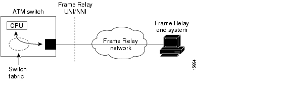
This chapter describes Frame Relay to ATM interworking and the required steps to configure the channelized Frame Relay port adapters in the Catalyst 8510 MSR and LightStream 1010 ATM switch routers. These port adapters facilitate interworking between a Frame Relay network, an ATM network, and network users. Existing Frame Relay users can also migrate to higher bandwidth ATM using channelized Frame Relay port adapters. Additionally, these port adapters extend the ATM network across a wide area over a frame-based serial line or intervening Frame Relay WAN.
Note
This chapter provides advanced configuration instructions for the Catalyst 8540 MSR, Catalyst 8510 MSR, and LightStream 1010 ATM switch routers. For an overview of Frame Relay to ATM interworking, refer to the Guide to ATM Technology. For complete descriptions of the commands mentioned in this chapter, refer to the ATM Switch Router Command Reference publication. For hardware installation and cabling instructions, refer to the ATM Port Adapter and Interface Module Installation Guide.
For a more information on how to configure your Frame Relay specific network equipment, refer to the Cisco IOS 12.0 publications on the Documentation CD-ROM.
This chapter includes the following sections:
•
•
•
•
•
•
•
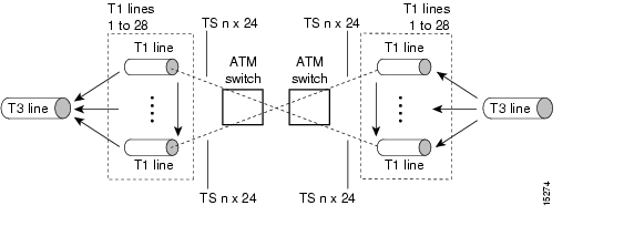
Configuring the Channelized DS3 Frame Relay Port Adapter
The channelized DS3 (CDS3) Frame Relay port adapter provides one physical port (45 Mbps). Each DS3 interface consists of 28 T1 lines multiplexed through a single T3 trunk. Each T1 line operates at 1.544 Mbps, which equates to 24 time slots (DS0 channels). A DS0 time slot provides 56 or 64 kbps of usable bandwidth. You can combine one or more DS0 time slots into a channel group to form a serial interface. A channel group provides n x 56 or 64 kbps of usable bandwidth, where n is the number of time slots, from 1 to 24. You can configure a maximum of 127 serial interfaces, or channel groups, per port adapter.
Figure 19-1 illustrates how a T3 trunk demultiplexes into 28 T1 lines that provide single or multiple time slots mapped across the ATM network. These time slots are then multiplexed to form an outgoing T3 bit stream.
Figure 19-1 T3/T1 Time Slot Mapping
Configuration Guidelines
In order to configure the CDS3 Frame Relay port adapter physical interface you need the following information:
•
•
•
Default CDS3 Frame Relay Port Adapter Interface Configuration
The following defaults are assigned to all CDS3 Frame Relay port adapter interfaces:
•
•
•
The following defaults are assigned to all T1 lines on the CDS3 Frame Relay port adapter:
•
•
•
•
•
Configuring the CDS3 Frame Relay Port Adapter Interface
To manually change any of your default configuration values, perform the following steps, beginning in global configuration mode:
Step 1
Switch(config)# controller t3 card/subcard/port
Switch(config-controller)#
Specifies the controller interface port and enters controller configuration mode.
Step 2
Switch(config-controller)# clock source {free-running | loop-timed | network-derived | reference}
Configures the type of clocking.
Step 3
Switch(config-controller)# framing {c-bit | m23}
Configures the CDS3 Frame Relay port adapter framing type.
Step 4
Switch(config-controller)# cablelength cablelength
Configures the CDS3 Frame Relay port adapter cable length.
Step 5
Switch(config-controller)# mdl {transmit {path | idle-signal | test-signal} | string {eic | lic | fic | unit | pfi | port | generator string}1
Configures the maintenance data link (MDL) message.
1 MDL messages are only supported when framing on the CDS3 Frame Relay port adapter is set for c-bit parity.
Example
The following example shows how to change the cable length configuration to 300 using the cablelength command.
Switch(config)# controller t3 3/0/0Switch(config-controller)# cablelength 300When using the cable length option, note that user-specified T3 cable lengths are structured into ranges as follows: 0 to 224 and 225 to 450. If you enter a cable length value that falls into one of these ranges, the range for that value is used.
For example, if you enter 150 feet, the 0 to 224 range is used. If you later change the cable length to 200 feet, there is no change because 200 is within the 0 to 224 range. However, if you change the cable length to 250, the 225 to 450 range is used. The actual number you enter is stored in the configuration file.
Configuring the T1 Lines on the CDS3 Frame Relay Port Adapter
To configure the T1 lines, perform the following steps, beginning in global configuration mode:
Configuring the Channel Group on the CDS3 Frame Relay Port Adapter
A channel group, also referred to as a serial interface, is configured on a T1 line by associating time slots to it. The channel group can have from 1 to 24 time slots (DS0s). The transmission rate or bandwidth of the channel group is calculated by multiplying the number of time slots times 56 kbps or 64 kbps.
Note
To configure the channel group on a T1 line, perform the following steps, beginning in global configuration mode:
Note
Example
The following example shows how to configure a channel group (with identifier 5), assigning time slots 1 through 5 on T1 line 1 using the channel-group command.
Switch(config)# controller t3 0/1/0Switch(config-controller)# channel-group 5 t1 1 timeslots 1-5Switch(config-controller)#
Note
Displaying the CDS3 Frame Relay Port Adapter Controller Information
To display the controller configuration, use one of the following EXEC commands:
show controllers t3 card/subcard/port[:t1-line] [brief | tabular]
Displays T3 and T1 configuration.
Example
The following example displays the configuration, status, and statistics of T1 line number 1 on controller 0/1/0:
Switch# show controllers t3 0/1/0:1 tabularT3 0/1/0:1 is up.
PAM state is Up1CT3 H/W Version: 1.71CT3 F/W Version: 2.7Transmitter is sending LOF Indication (RAI).Receiver has loss of frame.Framing is ESF, Line Code is B8ZS, Clock Source is line.INTERVAL LCV PCV CSS SELS LES DM ES BES SES UAS SS12:43-12:51 0 0 0 0 0 0 0 0 0 434 012:28-12:43 0 0 0 0 0 0 0 0 0 900 012:13-12:28 0 0 0 0 0 0 0 0 0 900 011:58-12:13 0 0 0 0 0 0 0 0 0 900 011:43-11:58 0 0 0 0 0 0 0 0 0 900 011:28-11:43 0 0 0 0 0 0 0 0 0 900 011:13-11:28 0 0 0 0 0 0 0 0 0 900 010:58-11:13 0 0 0 0 0 0 0 0 0 900 0Total 0 0 0 0 0 0 0 0 0 6300 0Deleting a Channel Group on the CDS3
This section describes two ways to delete a channel group on the CDS3 after it has been configured.
If you want to delete individual channel groups without shutting down the controller, use method one.
If you want to delete several channels groups on a controller, use method two. However, if you use method two, you must first shut down the controller, which shuts down all channel groups on the controller.
Method One
Perform the following steps, beginning in global configuration mode:
Method Two
Perform the following steps, beginning in global configuration mode:
Examples
The following example shuts down the serial interface and deletes channel group 1:
Switch(config)# interface serial 4/0/0:1Switch(config-if)# shutdownSwitch(config-if)# exitSwitch(config)# controller t3 4/0/0Switch(config-controller)# no channel-group 1Switch(config-controller)# endSwitch#The following example shuts down the T3 controller, deletes channel group 1, and then reenables the T3 controller:
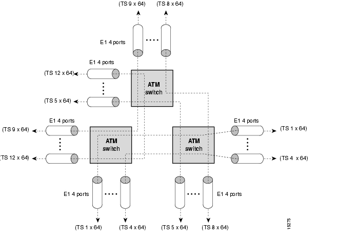
Switch(config)# controller t3 4/0/0Switch(config-controller)# shutdownSwitch(config-controller)# no channel-group 1Switch(config-controller)# no shutdownSwitch(config-controller)# endSwitch#Configuring the Channelized E1 Frame Relay Port Adapter
The channelized E1 (CE1) Frame Relay port adapter provides four physical ports. Each port supports up to 31 E1 serial interfaces, also referred to as channel groups, totalling 124 serial interfaces per port adapter. The E1 line operates at 2.048 Mbps, which is equivalent to 31 time slots (DS0 channels). The E1 time slot provides usable bandwidth of n x 64 kbps, where n is the time slot from 1 to 31.
Figure 19-2 illustrates how an E1 trunk (with four ports) provides single or multiple time slots mapped across the ATM network. Each time slot represents a single n x 64 circuit that transmits data at a rate of 64 kbps. Multiple n x 64 circuits can be connected to a single port, using separate time slots.
Figure 19-2 E1 Time Slot Mapping
Default CE1 Frame Relay Port Adapter Interface Configuration
The following defaults are assigned to all CE1 Frame Relay port adapter interfaces:
•
•
•
Configuring the CE1 Frame Relay Port Adapter Interface
If your CE1 Frame Relay port adapter needs to be configured, you must have the following information:
•
•
•
To manually change any of your default configuration values, perform the following steps, beginning in global configuration mode:
Example
The following example shows how to change the clock source to free-running using the clock source command.
Switch(config)# controller e1 1/0/0Switch(config-controller)# clock source free-runningConfiguring the Channel Group on the CE1 Frame Relay Port Adapter
A channel group, also referred to as a serial interface, is configured on an E1 line by associating time slots to it. The channel group can have from 1 to 31 time slots (DS0s). The transmission rate or bandwidth of the channel group is calculated by multiplying the number of time slots times 64 kbps.
To configure the channel group, perform the following steps, beginning in global configuration mode:
Example
The following example shows how to configure time slots 1 through 5 and 20 through 23 on E1 channel group 5 using the channel-group command.
Switch(config)# controller e1 0/1/0Switch(config-controller)# channel-group 5 timeslots 1-5, 20-23Displaying the CE1 Frame Relay Port Adapter Controller Information
To display your controller configuration, use the following EXEC command:
show controllers e1 card/subcard/port [brief | tabular]
Displays E1 controller configuration.
Example
The configuration for controller E1 is displayed in the following example:
Switch# show controllers e1 0/0/0 tabularE1 0/0/0 is up.E1 0/0/0 is up.PAM state is Up4CE1 H/W Version: 3.14CE1 F/W Version: 2.0No alarms detected.Framing is crc4, Line Code is HDB3, Clock Source is line.INTERVAL LCV PCV CS SELS LES DM ES BES SES UAS SS18:38-18:51 0 0 0 0 0 0 2 0 10 704 0Configuring Frame Relay to ATM Interworking Functions
You must follow the required steps to enable Frame Relay to ATM interworking on your ATM switch router. In addition, you can customize Frame Relay to ATM for your particular network needs and monitor Frame Relay-to-ATM connections. The following sections outline these tasks:
•
•
For information on how to customize your Frame Relay-to-ATM connections, see the "Configuring LMI" section and the "Configuring Frame Relay to ATM Resource Management" section .
Enabling Frame Relay Encapsulation on an Interface
To set Frame Relay encapsulation on the serial interface, perform the following steps, beginning in global configuration mode:
Frame Relay supports encapsulation of all supported protocols in conformance with RFC 1490, allowing interoperability between multiple vendors.
Note
Example
Switch(config)#interface serial 0/1/0:5Switch(config-if)# shutdownSwitch(config-if)#encapsulation frame-relay ietfSwitch(config-if)#no shutdownDisplaying Frame Relay Encapsulation
To display Frame Relay encapsulation, use the following user EXEC command:
Example:
The following example displays the Frame Relay encapsulation configuration on serial interface 0/1/0:5:
Switch# show interfaces serial 0/1/0:5Serial0/1/0:5 is up, line protocol is upHardware is FRPAM-SERIALMTU 4096 bytes, BW 320 Kbit, DLY 0 usec, rely 0/255, load 1/255Encapsulation FRAME-RELAY IETF, loopback not set, keepalive not setLast input never, output never, output hang neverLast clearing of "show interface" counters neverInput queue: 0/75/0 (size/max/drops); Total output drops:<information deleted>Configuring Frame Relay Serial Interface Type
To configure an interface as a data communications equipment (DCE) or Network-Network Interface (NNI) type, perform the following steps, beginning in global configuration mode:
Example
The following example shows how to configure Frame Relay interface type NNI for serial interface 0/1/0:5:
Switch(config)# interface serial 0/1/0:5Switch(config-if)# frame-relay intf-type nniDisplaying Frame Relay Interface Configuration
To display the Frame Relay interface configuration, use the following EXEC command:
Example
The Frame Relay configuration is displayed in the following example:
Switch# more system:running-configBuilding configuration...Current configuration:!version 11.3no service padno service password-encryption!hostname Switch!<information deleted>!interface Serial0/1/0:5no ip addressno ip directed-broadcastencapsulation frame-relay IETFno arp frame-relay<information deleted>Configuring LMI
Three industry-accepted standards are supported for addressing the Local Management Interface (LMI), including the Cisco specification. By default, the Cisco ILMI option is active on your Frame Relay interface.
Configuring the LMI Type
To manually set an LMI type on your Frame Relay port adapter, perform the following steps, beginning in global configuration mode:
Example
The following example changes the LMI type to ansi on serial interface 1/1/0:1:
Switch(config)# interface serial 1/1/0:1Switch(config-if)# frame-relay lmi-type ansiSwitch(config-if)# endSwitch# copy system:running-config nvram:startup-configDisplaying LMI Type
To display the LMI type configuration, perform the following task in user EXEC mode:
show frame-relay lmi interface serial card/subcard/port:cgn
Displays LMI type configuration.
Example
The following example displays the LMI type configuration of a Frame Relay port adapter:
Switch> show frame-relay lmi interface serial 1/1/0:1Invalid Unnumbered info 0 Invalid Prot Disc 0Invalid dummy Call Ref 0 Invalid Msg Type 0Invalid Status Message 0 Invalid Lock Shift 0Invalid Information ID 0 Invalid Report IE Len 0Invalid Report Request 0 Invalid Keep IE Len 0Num Status Enq. Rcvd 5103 Num Status msgs Sent 5103Num Update Status Rcvd 0 Num St Enq. Timeouts 10Num Status Enq. Sent 5118 Num Status msgs Rcvd 5103Num Update Status Sent 0 Num Status Timeouts 14Configuring the LMI Keepalive Interval
A keepalive interval must be set to configure the LMI. By default, this interval is 10 seconds and, per the LMI protocol, must be set as a positive integer that is less than the lmi-t392dce interval set on the interface of the neighboring switch.
To set the keepalive interval, perform the following steps, beginning in global configuration mode:
Example
The following example configures the LMI keepalive interval to 30 seconds:
Switch(config)# interface serial 1/1/0:1Switch(config-if)# keepalive 30Displaying LMI Keepalive Interval
To display the LMI keepalive interval, perform the following task in user EXEC mode:
show frame-relay lmi interface serial card/subcard/port:cgn
Displays LMI keepalive interval.
Example
The following example displays the LMI keepalive interval of a Frame Relay port adapter:
Switch> show interfaces serial 1/1/0:1Serial1/1/0:1 is up, line protocol is upHardware is FRPAM-SERIALMTU 4096 bytes, BW 640 Kbit, DLY 0 usec, rely 255/255, load 1/255LMI enq sent 5163, LMI stat recvd 5144, LMI upd recvd 0, DTE LMI upLMI enq recvd 5154, LMI stat sent 5154, LMI upd sent 0, DCE LMI upLMI DLCI 1023 LMI type is CISCO frame relay NNILast input 00:00:04, output 00:00:20, output hang never<Information Deleted>Configuring the LMI Polling and Timer Intervals (Optional)
You can set various optional counters, intervals, and thresholds to fine-tune the operation of your LMI on your Frame Relay devices. Set these attributes by performing one or more of the following steps, beginning in global configuration mode:
Example
The following example shows how to change the default polling verification timer on a Frame Relay interface to 20 seconds using the frame-relay lmi-t392dce command.
Switch(config)# interface serial 0/1/0:5Switch(config-if)# frame-relay lmi-t392dce 20Displaying Frame Relay Serial Interface
To display information about a serial interface, perform the following task in user EXEC mode:
show interfaces serial card/subcard/port:cgn
Displays Frame Relay serial interface configuration.
Example
The following example displays serial interface configuration information for an interface with Cisco LMI enabled:
Switch> show interfaces serial 0/1/0:5Serial 0/1/0:5 is up, line protocol is upHardware is FRPAM-SERIALMTU 4096 bytes, BW 1536 Kbit, DLY 0 usec, rely 229/255, load 14/255Encapsulation FRAME-RELAY IETF, loopback not set, keepalive set (10 sec)LMI enq sent 0, LMI stat recvd 0, LMI upd recvd 0<information deleted>Displaying LMI Statistics
To display statistics about the LMI, perform the following task in user EXEC mode:
show frame-relay lmi interface serial card/subcard/port:cgn
Displays LMI statistics.
Example
The following example displays the LMI statistics of a Frame Relay port adapter with an NNI interface:
Switch> show frame-relay lmi interface serial 0/1/0:5LMI Statistics for interface serial 0/1/0:5 (Frame Relay NNI) LMI Type = CiscoInvalid Unnumberred info 0 Invalid Prot Disc 0Invalid dummy Call Ref 0 Invalid msg Type 0Invalid Status Message 0 Invalid Lock Shift 0Invalid Information ID 0 Invalid Report IE Len 0Invalid Report Request 0 Invalid Keep IE Len 0Num Status Enq. Rcvd 11 Num Status msgs Sent 11Num Update Status Rcvd 0 Num St Enq Timeouts 0Num Status Enq. Sent 10 Num Status msgs Rcvd 10Num Update Status Sent 0 Num Status Timeouts 0Configuring Frame Relay to ATM Resource Management
This section describes the following resource management tasks specifically for your Frame Relay to ATM interworking network needs:
•
•
•
For information about how to configure your ATM Connection Traffic Table rows, see the "Configuring the Connection Traffic Table" section in the "Configuring Resource Management" chapter.
Configuring Frame Relay-to-ATM Connection Traffic Table Rows
A row in the Frame Relay-to-ATM Connection Traffic Table (CTT) must be created for each unique combination of Frame Relay traffic parameters. All Frame Relay to ATM interworking virtual connections then provide traffic parameters for each row in the table per flow (receive and transmit). Multiple virtual connections can refer to the same traffic table row.
The Frame Relay traffic parameters (specified in the command used to create the row) are converted into equivalent ATM traffic parameters. Both parameters are stored internally and used for interworking virtual connections.
The formula used for Frame Relay to ATM traffic conversions are specified in the B-ICI specification, V2.0. Use a frame size (n) of 250 bytes and a header size of 2 bytes. See Table 19-1.
Table 19-1 Frame Relay to ATM Traffic Conversion
Peak Cell Rate (0+1) (Cells Per Second) =
Peak Information Rate1 /8 * (6/260)
Sustainable Cell Rate (0) (Cells Per Second) =
Committed Information Rate1 /8 * (6/250)
Maximum Burst Size (0) (Cells) =
(Committed Burst Size2 /8 * (1/(1-Committed Information Rate/Peak Information Rate)) + 1) * (6/250)
1 In bits per second.
2 In bits.
PVC Connection Traffic Rows
Permanent virtual channel (PVC) connection traffic rows, or stable rows, are used to specify traffic parameters for PVCs.
Note
SVC Connection Traffic Rows
SVC connection traffic rows, or transient rows, are used by the signalling software to obtain traffic parameters for soft SVCs.
Note
To make the CTT management software more efficient, the CTT row-index space is split into space allocated by the CLI/SNMP and signalling. See Table 19-2.
Table 19-2 CTT Row-Index Allocation
CLI/SNMP
1 through 1,073,741,823
Signalling
1,073,741,824 through 2,147,483,647
Predefined Rows
Table 19-3 describes the predefined row:
Creating a Frame Relay-to-ATM CTT Row
To create a Frame Relay-to-ATM CTT row, perform the following task in global configuration mode:
frame-relay connection-traffic-table-row [index row-index] cir-value bc-value pir-value be-value {abr | vbr-nrt | ubr} [atm-row-index]
Configures a Frame Relay-to-ATM CTT row.
If you do not specify an index row number, the system software determines if one is free. The index row number is then displayed in the allocated index field if the command is successful.
If the ATM row index is not specified, system software tries to use the same row index used by Frame Relay. If not possible, a free ATM row index is used.
Example
The following example shows how to configure a Frame Relay-to-ATM CTT row with non-real-time variable bit rate (VBR-NRT) service category, committed information rate of 64000 bits per second, a peak information rate of 1536000 bits per second, and a committed burst size of 8192 bits per second:
Switch(config)# frame-relay connection-traffic-table-row 64000 8192 1536000 vbr-nrtAllocated index = 64000Switch(config)#Displaying the Frame Relay-to-ATM Connection Traffic Table
To display the Frame Relay-to-ATM CTT configuration, use the following EXEC command:
show frame-relay connection-traffic-table-row [from-row row | row row]
Displays the Frame Relay-to-ATM CTT configuration.
Example
The following example shows how to display the Frame Relay-to-ATM CTT configuration table:
Switch# show frame-relay connection-traffic-table-rowRow cir bc be pir FR-ATM Service Category ATM row100 64000 32768 32768 64000 vbr-nrt 100Configuring the Interface Resource Management Tasks
The following resource management tasks configure queue thresholds, committed burst size, and service overflow on Frame Relay interfaces. To change any of these interface parameters, perform the following steps, in interface configuration mode:
Note
Displaying Frame Relay Interface Resources
To display your Frame Relay interface resource configuration, use the following EXEC command:
show frame-relay interface resource serial card/subcard/port:cgn
Displays resource allocation on a Frame Relay interface.
Example
The resource information for Frame Relay serial interface 0/1/0:5 is displayed in the following example:
Switch# show frame-relay interface resource serial 0/1/0:5Encapsulation: FRAME-RELAYInput queues (PAM to switch fabric):Discard threshold: 87% vbr-nrt, 87% abr, 87% ubrMarking threshold: 75% vbr-nrt, 75% abr, 75% ubrOutput queues (PAM to line):Discard threshold: 87% vbr-nrt, 87% abr, 87% ubrMarking threshold: 75% vbr-nrt, 75% abr, 75% ubrOverflow servicing for VBR: enabledResource Management state:Available bit rates (in bps):320000 vbr-nrt RX, 320000 vbr-nrt TX320000 abr RX, 320000 abr TX320000 ubr RX, 320000 ubr TXAllocated bit rates (in bps):0 vbr-nrt RX, 0 vbr-nrt TX0 abr RX, 0 abr TX0 ubr RX, 0 ubr TXConfiguring Frame Relay-to-ATM Virtual Connections
This section describes how to configure virtual connections (VCs) for Frame Relay to ATM interworking and Frame Relay-to-Frame Relay switching.
The tasks to configure virtual connections are described in the following sections:
•
•
•
•
•
Configuration Guidelines
Perform the following tasks in a prescribed order before configuring a Frame Relay to ATM interworking permanent virtual channel (PVC), soft PVC, or a Frame Relay-to-Frame Relay PVC:
Step 1
Step 2
Step 3
Step 4
Step 5
Characteristics and Types of Virtual Connections
The characteristics of the Frame Relay to ATM interworking VC, established when the VC is created, include the following:
•
•
•
•
•
•
These switching features can be turned off with the interface configuration commands.
Note
Note
Table 19-4 lists the types of supported virtual connections.
Configuring Frame Relay to ATM Network Interworking PVCs
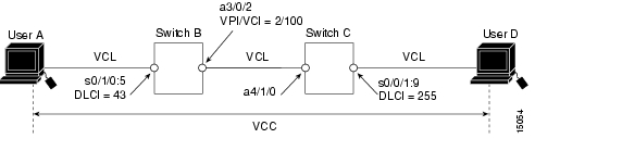
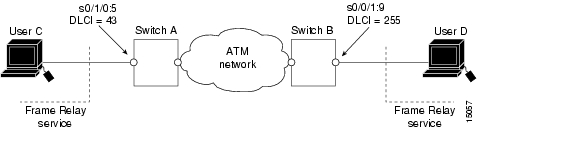
This section describes configuring Frame Relay to ATM network interworking PVCs. This type of connection establishes a bidirectional facility that transfers Frame Relay traffic between two Frame Relay users through an ATM network.
Figure 19-3 shows an example of a Frame Relay to ATM network interworking PVC between Frame Relay User A and ATM User D through an ATM network.
Figure 19-3 Network Interworking PVC Example
To configure a Frame Relay to ATM network interworking PVC, perform the following steps, beginning in global configuration mode:
Step 1
Switch(config)# interface serial card/subcard/port:cgn1
Switch(config-if)#
Selects the interface to be configured.
Step 2
Switch(config-if)# frame-relay pvc dlci2 [upc {pass | drop}] [rx-cttr index] [tx-cttr index] network [clp-bit {0 | 1 | map-de}] [de-bit {map-de | map-clp-or-de}] [interface atm card/subcard/port vpi vci [upc upc] [pd {off | on}] [rx-cttr index] [tx-cttr index]]
Configures a Frame Relay to ATM network interworking PVC.
1 The serial interface is created with the channel-group command and configured using the encapsulation frame-relay ietf command. cgn is the channel group number of a channel group configured using the channel-group command.
2 The dlci value appears in the Conn-Id and X-Conn-Id columns of the show vc command.
Note
Note
Examples
The following example shows how to configure the internal cross-connect Frame Relay to ATM network interworking PVC on Switch B between serial interface 0/1/0:5, DLCI = 43 and ATM interface 3/0/2, VPI = 2, VCI = 100 (see Figure 19-3):
Switch-B(config)# interface serial 0/1/0:5Switch-B(config-if)# frame-relay pvc 43 network interface atm 3/0/2 2 100The following example shows how to configure the internal cross-connect PVC on Switch C between serial interface 0/0/1:9, DLCI = 255 and ATM interface 4/1/0, VPI = 2, VCI = 100:
Switch-C(config)# interface serial 0/0/1:9Switch-C(config-if)# frame-relay pvc 255 network interface atm 4/1/0 2 100
Note
Displaying Frame Relay to ATM Network Interworking PVCs
To display the network interworking configuration, use the following EXEC command:
show vc [interface {atm card/subcard/port [vpi vci] | serial card/subcard/port:cgn [dlci]}]
Shows the PVC interface configuration.
Example
The following example displays the Switch B PVC configuration for serial interface 0/1/0:5:
Switch-B# show vc interface serial 0/1/0:5Interface Conn-Id Type X-Interface X-Conn-Id Encap StatusSerial0/1/0:5 43 PVC ATM3/0/2 2/100 UPThe following example displays the configuration of the Switch B PVC on serial interface 0/1/0:5, DLCI = 43:
Switch-B# show vc interface serial 0/1/0:5 43Interface: Serial0/1/0:5, Type: FRPAM-SERIALDLCI = 43 Status : ACTIVEConnection-type: PVCCast-type: point-to-pointUsage-Parameter-Control (UPC): tag-droppvc-create-time : 00:00:10 Time-since-last-status-change : 00:00:03Interworking Function Type : networkde-bit Mapping : map-clp-or-de clp-bit Mapping : map-deATM-P Interface: ATM-P0/1/0, Type: ATM-PSEUDOATM-P VPI = 82 ATM-P VCI = 11ATM-P Connection Status: UPCross-connect-interface: ATM0/0/0, Type: oc3suniCross-connect-VPI = 2Cross-connect-VCI = 100Cross-connect-UPC: passCross-connect OAM-configuration: disabledCross-connect OAM-state: Not-applicabletx Frames : 0 Rx Frames : 0tx Bytes : 0 Rx Bytes : 0tx Frames Discarded : 0 Rx Frames Discarded : 0tx Bytes Discarded : 0 Rx Bytes Discarded : 0Rx connection-traffic-table-index: 100Rx service-category: VBR-NRT (Non-Realtime Variable Bit Rate)Rx pir: 64000Rx cir: 64000Rx Bc : 32768Rx Be : 32768Tx connection-traffic-table-index: 100Tx service-category: VBR-NRT (Non-Realtime Variable Bit Rate)Tx pir: 64000Tx cir: 64000Tx Bc : 32768Tx Be : 32768Configuring Frame Relay to ATM Service Interworking PVCs
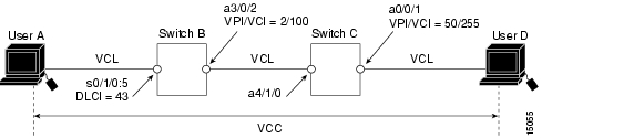
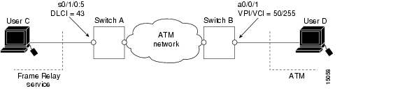
This section describes configuring Frame Relay to ATM service interworking permanent virtual channels (PVCs). A Frame Relay to ATM service interworking PVC is established as a bidirectional facility to transfer Frame Relay to ATM traffic between a Frame Relay user and an ATM user. The upper user protocol encapsulation (FRF.3, RFC 1483, RFC 1490, RFC 1577) mapping can be enabled with the translation option of the frame-relay pvc command.
Figure 19-4 shows an example of a Frame Relay to ATM service interworking PVC between Frame Relay User A and ATM User D through an ATM network.
Figure 19-4 Service Interworking PVC Example
Note
To configure a Frame Relay to ATM service interworking PVC, perform the following steps beginning in global configuration mode:
Step 1
Switch(config)# interface serial card/subcard/port:cgn
Switch(config-if)#
Selects the interface to be configured.
Step 2
Switch(config-if)# frame-relay pvc dlci [upc {pass | drop}] [rx-cttr index] [tx-cttr index] service {transparent | translation} [clp-bit {0 | 1 | map-de}] [de-bit {0 | 1 | map-clp}] [efci-bit {0 | map-fecn}] [interface atm card/subcard/port vpi [vci | any-vci1 ] [upc {pass | drop}] [pd {off | on}] [rx-cttr index] [tx-cttr index] [encap aal-encap] [inarp minutes]]
Configures a Frame Relay to ATM service interworking PVC.
1 The any-vci option is only available on interface atm0. See note below.
Note
Note
Examples
The following example shows how to configure the internal cross-connect PVC on Switch B between serial interface 0/1/0:5, DLCI = 43, and ATM interface 3/0/2, VPI = 2, VCI = 100 (with the translation option):
Switch-B(config)# interface serial 0/1/0:5Switch-B(config-if)# frame-relay pvc 43 service translation interface atm 3/0/2 2 100The following example shows how to configure the internal cross-connect PVC on Switch C between ATM interface 4/1/0, VPI = 2, VCI = 100 and ATM interface 0/0/1, VPI 50, VCI = 255:
Switch-C(config)# interface atm 4/1/0Switch-C(config-if)# atm pvc 2 100 interface atm 0/0/1 50 255Each subsequent VC cross connection and link must be configured until the VC is terminated to create the entire PVC.
Note
Displaying Frame Relay to ATM Service Interworking PVCs
To display the service interworking PVC configuration, use the following EXEC commands:
Configuring Terminating Frame Relay to ATM Service Interworking PVCs
This section describes configuring terminating Frame Relay to ATM service interworking permanent virtual channels (PVCs). This type of terminating connection provides the connection from IP over Frame Relay to the ATM switch router used for IP over ATM and network management.
Figure 19-5 shows an example of transmit and terminating connections.
Figure 19-5 Frame Relay to ATM Transmit and Terminating Connections
Terminating connections are configured using the frame-relay pvc command; however, all switch terminating connections use atm0 to connect to the ATM switch route processor.
To configure terminating Frame Relay to ATM service interworking PVC connections, perform the following steps, beginning in global configuration mode:
Step 1
Switch(config)# interface serial card/subcard/port:cgn
Switch(config-if)#
Selects the interface to be configured.
Step 2
Switch(config-if)# frame-relay pvc dlci [upc {pass | drop}] [rx-cttr index] [tx-cttr index] service {transparent | translation} [clp-bit {0 | 1 | map-de}] [de-bit {0 | 1 | map-clp}] [efci-bit {0 | map-fecn}] [interface atm card/subcard/port vpi vci | any-vci1 ] [upc {pass | drop}] [pd {off | on}] [rx-cttr index] [tx-cttr index] [encap aal-encap] [inarp minutes]]
Configures a Frame Relay to ATM service interworking PVC.
1 The any-vci option is only available on interface atm0.
Example
The following example shows how to configure the internal cross-connect PVC on Switch B between serial interface 0/1/0:5, DLCI = 50, and the terminating connection on ATM interface 0, VPI = 0, and an unspecified VCI:
Switch-B(config)# interface serial 0/1/0:5Switch-B(config-if)# frame-relay pvc 50 service translation interface atm 0 0 any-vci encap aal5snap
Note
Displaying Terminating Frame Relay to ATM Service Interworking PVCs
To display the service interworking PVC configuration, use the following EXEC commands:
Note
Configuring Frame Relay Transit PVCs
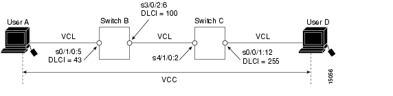
This section describes configuring internal cross-connect Frame Relay-to-Frame Relay transit permanent virtual channels (PVCs). This type of PVC is used to establish a bidirectional facility to transfer Frame Relay traffic between two Frame Relay users. Figure 19-6 shows a Frame Relay transit PVC between Frame Relay users A and D.
Figure 19-6 Transit PVC Example
To configure a Frame Relay transit PVC, perform the following steps, beginning in global configuration mode:
Examples
The following example shows how to configure the internal cross-connect Frame Relay PVC on Switch B between serial interface 0/1/0:5, DLCI = 43, and serial interface 3/0/2:6, DLCI = 100:
Switch-B(config)# interface serial 0/1/0:5Switch-B(config-if)# frame-relay pvc 43 interface serial 3/0/2:6 100The following example shows how to configure the internal cross-connect Frame Relay on Switch C between serial interface 4/1/0:2, DLCI = 100,0 and serial interface 0/0/1:12, DLCI = 255:
Switch-C(config)# interface serial 4/1/0:2Switch-C(config-if)# frame-relay pvc 100 interface serial 0/0/1:12 255Each subsequent VC cross-connection and link must be configured until the VC is terminated to create the entire VCC.
To display Frame Relay transit PVCs, use the show interfaces and show vc commands.
Configuring Frame Relay Soft PVC Connections
This section describes configuring Frame Relay to ATM interworking soft permanent virtual channels (soft PVC) connections.
You can configure the following soft PVC connections:
•
•
•
Configuration Guidelines
These guidelines are appropriate for both network and service interworking soft PVC connections.
Note
Perform the following steps, and refer to Figure 19-7:
Step 1
Step 2
Step 3
Step 4
Step 5
Step 6
If the destination side of the soft PVC is an ATM interface, choose an available VPI/VCI value.
Step 7
Note
Step 8
Configuring Frame Relay-to-Frame Relay Network Interworking Soft PVCs
This section describes how to configure a Frame Relay-to-Frame Relay network interworking soft PVC terminating on two Frame Relay interfaces. Figure 19-7 shows a Frame Relay-to-Frame Relay network interworking soft PVC between Switch A and Switch B.
Figure 19-7 Frame Relay-to-Frame Relay Network Interworking Soft PVC Example
To configure a Frame Relay-to-Frame Relay network interworking soft PVC, perform the following steps, beginning in EXEC mode:
The previous configuration steps are illustrated in the following section.
Note
Frame Relay-to-Frame Relay Interworking Soft PVC Configuration Example
This section provides an example of a Frame Relay-to-Frame Relay network interworking soft PVC configured between Switch A and Switch B, as shown in Figure 19-7. The source (active) side is serial interface 0/1/0:5 on Switch A.
Step 1
Switch-A# show vc interface serial 0/1/0:5Interface Conn-Id Type X-Interface X-Conn-Id Encap StatusSerial0/1/0:5 54 SoftVC Serial3/0/0:3 54 SoftVC UPSerial0/1/0:5 55 SoftVC Serial3/0/0:2 55 SoftVC UPSerial0/1/0:5 56 SoftVC ATM0/1/3 0/45 SVC UPSerial0/1/0:5 66 SoftVC ATM1/1/0 0/100 SoftVC UPStep 2
Step 3
Switch-B# show atm addressesSwitch Address(es):47.00918100000000E01E798803.00E01E808601.00 activeSoft VC Address(es) :47.0091.8100.0000.00e0.1e79.8803.4000.0c80.0000.00 ATM1/0/047.0091.8100.0000.00e0.1e79.8803.4000.0c80.0010.00 ATM1/0/147.0091.8100.0000.00e0.1e79.8803.4000.0c80.0020.00 ATM1/0/247.0091.8100.0000.00e0.1e79.8803.4000.0c80.0030.00 ATM1/0/3<information deleted>Soft VC Address(es) for Frame Relay Interfaces :47.0091.8100.0000.00e0.1e79.8803.4000.0c81.8010.00 Serial0/0/1:947.0091.8100.0000.00e0.1e79.8803.4000.0c81.8020.00 Serial0/0/1:10ILMI Switch Prefix(es):47.0091.8100.0000.00e0.1e79.8803<information deleted>Step 4
Switch-B# show vc interface serial 0/0/1:9Interface Conn-Id Type X-Interface X-Conn-Id Encap StatusSerial0/0/1:9 44 SoftVC Serial3/0/0:3 54 SoftVC UPSerial0/0/1:9 45 SoftVC Serial3/0/0:2 55 SoftVC UPSerial0/0/1:9 76 SoftVC ATM0/1/3 0/45 SVC UPSerial0/0/1:9 86 SoftVC ATM1/1/0 0/100 SoftVC UPStep 5
Switch-A(config)# interface serial 0/1/0:5Switch-A(config-if)# frame-relay soft-vc 43 dest-address47.0091.8100.0000.00e0.1e79.8803.4000.0c81.8010.00 dlci 255
Note
After you complete the soft VC configuration, proceed to the "Display Frame Relay Internetworking Soft PVCs" section and verify the connection.
Configuring Frame Relay to ATM Network Interworking Soft PVCs
This section describes how to configure a Frame Relay to ATM network interworking soft permanent virtual channel (soft PVC). Figure 19-8 shows a Frame Relay to ATM network interworking soft PVC between Switch A and Switch B.
Figure 19-8 Frame Relay to ATM Network Interworking Soft PVC Example
To configure a Frame Relay to ATM network interworking soft PVC, perform the following steps, beginning in EXEC mode:
The previous configuration steps are illustrated in the following section.
Note
Frame Relay to ATM Network Interworking Soft PVC Configuration Example
This section provides an example of a network interworking soft PVC configured between switch A and Switch B and shown in Figure 19-9. The source (active) side is serial interface 0/1/0:5 on Switch A.
Step 1
Switch-A# show vc interface serial 0/1/0:5Interface Conn-Id Type X-Interface X-Conn-Id Encap StatusSerial0/1/0:5 54 SoftVC Serial3/0/0:3 54 SoftVC UPSerial0/1/0:5 55 SoftVC Serial3/0/0:2 55 SoftVC UPSerial0/1/0:5 56 SoftVC ATM0/1/3 0/45 SVC UPSerial0/1/0:5 66 SoftVC ATM1/1/0 0/100 SoftVC UPStep 2
Switch-B# show atm addressesSwitch Address(es):47.00918100000000E01E199904.00E01E808601.00 activeSoft VC Address(es) :47.0091.8100.0000.00e0.1e19.9904.4000.0c80.0000.00 ATM0/0/047.0091.8100.0000.00e0.1e19.9904.4000.0c80.0010.00 ATM0/0/147.0091.8100.0000.00e0.1e19.9904.4000.0c80.0020.00 ATM0/0/247.0091.8100.0000.00e0.1e19.9904.4000.0c80.0030.00 ATM0/0/3<information deleted>Step 3
Switch-B# show vc interface atm 0/0/1Interface Conn-Id Type X-Interface X-Conn-Id Encap StatusATM0/0/1 0/5 PVC ATM2/0/0 0/58 QSAAL UPATM0/0/1 0/16 PVC ATM2/0/0 0/44 ILMI UPATM0/0/1 0/18 PVC ATM2/0/0 0/71 PNNI UPStep 4
Switch-A(config)# interface serial0/1/0:5Switch-A(config-if)# frame-relay soft-vc 43 dest-address 47.0091.8100.0000.00e0.1e19.9904.4000.0c80.0010.00 vc 50 255 networkAfter you complete the soft VC configuration, go to the "Display Frame Relay Internetworking Soft PVCs" section and verify the connection.
Configuring Frame Relay to ATM Service Interworking Soft PVCs
This section describes configuring a Frame Relay to ATM service interworking soft PVC terminating on an ATM interface. Figure 19-9 shows a Frame Relay to ATM service interworking soft PVC between Switch A and Switch B.
Figure 19-9 Frame Relay to ATM Service Interworking Soft PVC Example
To configure a Frame Relay to ATM service interworking soft PVC, perform the following steps, beginning in EXEC mode:
Note
Note
Frame Relay to ATM Service Interworking Soft PVC Configuration Example
Use the following steps to configure the service interworking soft PVC between Switch A and switch B as shown in Figure 19-9.
Note
Step 1
Switch-A# show vc interface serial 0/1/0:5Interface Conn-Id Type X-Interface X-Conn-Id Encap StatusSerial0/1/0:5 54 SoftVC Serial3/0/0:3 54 SoftVC UPSerial0/1/0:5 55 SoftVC Serial3/0/0:2 55 SoftVC UPSerial0/1/0:5 56 SoftVC ATM0/1/3 0/45 SVC UPSerial0/1/0:5 66 SoftVC ATM1/1/0 0/100 SoftVC UPStep 2
Switch-B# show atm addressesSwitch Address(es):47.00918100000000E01E199904.00E01E808601.00 activeSoft VC Address(es) :47.0091.8100.0000.00e0.1e19.9904.4000.0c80.0000.00 ATM0/0/047.0091.8100.0000.00e0.1e19.9904.4000.0c80.0020.00 ATM0/0/247.0091.8100.0000.00e0.1e19.9904.4000.0c80.0030.00 ATM0/0/3<information deleted>Step 3
Switch-B# show vc interface atm 0/0/1Interface Conn-Id Type X-Interface X-Conn-Id Encap StatusATM0/0/1 0/5 PVC ATM2/0/0 0/58 QSAAL UPATM0/0/1 0/16 PVC ATM2/0/0 0/44 ILMI UPATM0/0/1 0/18 PVC ATM2/0/0 0/71 PNNI UPStep 4
Switch-A(config)# interface serial 0/1/0:5Switch-A(config-if)# frame-relay soft-vc 43 dest-address 47.0091.8100.0000.00e0.1e19.9904.4000.0c80.0010.00 vc 50 255 service transparentAfter you complete the soft VC configuration, go to the "Display Frame Relay Internetworking Soft PVCs" section and verify the connection.
Display Frame Relay Internetworking Soft PVCs
To display your Frame Relay internetworking soft PVCs configuration, use the following EXEC command:
show vc [interface {atm card/subcard/port [vpi vci] | serial card/subcard/port:cgn [dlci]}]
Shows the PVC interface configuration.
Examples
The following example displays serial interface 1/1/0:2 soft PVC status:
Switch# show vc interface serial 1/1/0:2Interface Conn-Id Type X-Interface X-Conn-Id Encap StatusThe following example displays ATM interface 0/0/0 soft PVC status:
Switch# show vc interface atm 0/0/0Interface Conn-Id Type X-Interface X-Conn-Id Encap StatusATM0/0/0 0/5 PVC ATM2/0/0 0/43 QSAAL UPATM0/0/0 0/16 PVC ATM2/0/0 0/35 ILMI UPATM0/0/0 0/200 PVC ATM0/0/1 0/200 DOWNConfiguring the Soft PVC Route Optimization Feature
This section describes the soft permanent virtual channel (soft PVC) route optimization feature for Frame Relay interfaces. Most soft PVCs have a much longer lifetime than switched virtual channels (SVCs). The route chosen during the soft connection setup remains the same even though the network topology might change.
Soft connections, with the route optimization percentage threshold set, provide the following features:
•
•
Note
Configuring a Frame Relay Interface with Route Optimization
Soft PVC route optimization must be enabled and configured to determine the point at which a better route is found and the old route is reconfigured.
To enable and configure a Frame Relay interface with route optimization, perform the following steps, beginning in global configuration mode:
Example
The following example shows how to configure an interface with a route optimization interval configured as every 30 minutes between the hours of 6:00 P.M. and 5:00 A.M.:
Switch(config)# atm route-optimization percentage-threshold 45Switch(config)# interface serial 1/0/0:1Switch(config-if)# atm route-optimization soft-connection interval 30 time-of-day 18:00 5:00Displaying a Frame Relay Interface Route Optimization Configuration
To display the Frame Relay interface route optimization configuration, use the following privileged EXEC commands:
show running-config
Shows the serial interface configuration route optimization configuration.
show interfaces [serial card/subcard/port:cgn]
Shows the serial interface configuration.
Example
The following example shows the route optimization configuration of serial interface 1/0/0:1:
Switch# show running-configBuilding configuration...<information deleted>!interface Serial1/0/0:1description Engineering connectionsno ip addressno ip directed-broadcastencapsulation frame-relay IETFno arp frame-relayno snmp trap link-statusframe-relay intf-type nniatm route-optimization soft-connection interval 30 time-of-day 18:0 5:0!Switch# show interfaces serial 3/0/0:1Serial3/0/0:1 is up, line protocol is upHardware is FRPAM-SERIALMTU 4096 bytes, BW 1536 Kbit, DLY 0 usec, rely 128/255, load 1/255Encapsulation FRAME-RELAY IETF, loopback not set, keepalive not setLast input 00:00:08, output never, output hang neverLast clearing of "show interface" counters neverInput queue: 0/75/0 (size/max/drops); Total output drops: 0Queueing strategy: weighted fairOutput queue: 0/1000/64/0 (size/max total/threshold/drops)Conversations 0/0/256 (active/max active/max total)Reserved Conversations 0/0 (allocated/max allocated)5 minute input rate 0 bits/sec, 0 packets/sec5 minute output rate 0 bits/sec, 0 packets/sec12963 packets input, 12963 bytes, 0 no bufferReceived 0 broadcasts, 0 runts, 0 giants, 0 throttles12963 input errors, 7638 CRC, 0 frame, 0 overrun, 0 ignored, 0 abort0 packets output, 0 bytes, 0 underruns0 output errors, 0 collisions, 0 interface resets0 output buffer failures, 0 output buffers swapped out2 carrier transitionsTimeslots(s) Used: 1-24 on T1 1Frames Received with:DE set: 0, FECN set :0, BECN set: 0Frames Tagged :DE: 0, FECN: 0 BECN: 0Frames Discarded Due to Alignment Error: 0Frames Discarded Due to Illegal Length: 0Frames Received with unknown DLCI: 0Frames with illegal Header : 0Transmit Frames with FECN set :0, BECN Set :0Transmit Frames Tagged FECN : 0 BECN : 0Transmit Frames Discarded due to No buffers : 0Default Upc Action : tag-dropDefault Bc (in Bits) : 32768Soft vc route optimization interval = 50 minutesSoft vc route optimization time-of-day range = (20:10 - 23:40)Respecifying Existing Frame Relay to ATM Interworking Soft PVCs
For existing Frame Relay to ATM interworking soft permanent virtual channels (soft PVCs), a connection is disabled to prevent an explicit path from being used for routing while it is reconfigured. The redo_explicit keyword is used to allow respecifying of the explicit path configuration without bringing down connections. Existing connections remain unaffected unless a reroute takes place. If rerouting occurs, the new explicit path configuration takes affect.
To enable or disable soft PVC and respecify explicit-path configuration, use the following interface command:
![]()
![]()
![]()
![]()
![]()
![]()
![]()
![]()
Posted: Mon Oct 11 09:29:11 PDT 2004
All contents are Copyright © 1992--2004 Cisco Systems, Inc. All rights reserved.
Important Notices and Privacy Statement.