|
|

Table Of Contents
Configuring Circuit Emulation Services
Overview of CES T1/E1 Interfaces
Functions Supported by CES Modules
Framing Formats and Line Coding Options for CES Modules
Default CES T1/E1 Interface Configuration
Configuring CES T1/E1 Interfaces
General Guidelines for Creating Soft PVCs for Circuit Emulation Services
Configuring T1/E1 Unstructured Circuit Emulation Services
Overview of Unstructured Circuit Emulation Services
Configuring a Hard PVC for Unstructured CES
Verifying a Hard PVC for Unstructured CES
Configuring a Soft PVC for Unstructured CES
Verifying a Soft PVC for Unstructured CES
Configuring T1/E1 Structured (n x 64) Circuit Emulation Services
Overview of Structured Circuit Emulation Services
Configuring a Hard PVC for Structured CES
Verifying a Hard PVC for Structured CES
Configuring a Hard PVC for Structured CES with a Shaped VP Tunnel
Verifying a Hard PVC for Structured CES with a Shaped VP Tunnel
Configuring a Soft PVC for Structured CES
Verifying a Soft PVC for Structured CES
Configuring a Soft PVC for Structured CES with CAS Enabled
Verifying a Soft PVC for Structured CES with CAS Enabled
Configuring a Soft PVC for Structured CES with CAS and On-Hook Detection Enabled
Verifying a Soft PVC for Structured CES with CAS and On-Hook Detection Enabled
Creating Multiple Structured Soft PVCs on the Same CES Port
Verifying the Creation of Multiple Structured Soft PVCs on the Same CES Port
Reconfiguring a Previously Established Circuit
Deleting a Previously Established Circuit
Verifying Deletion of a Previously Established Circuit
Configuring SGCP on the Entire Switch
Configuring CES Circuits for SGCP
Configuring SGCP Request Handling
Configuring Call-Agent Address
Configuring Circuit Emulation Services
This chapter describes circuit emulation services (CES) and how to configure the CES T1/E1 port adapters in the Catalyst 8540 MSR, Catalyst 8510 MSR, and LightStream 1010 ATM switch routers. You can use CES T1/E1 port adapters for links that require constant bit rate (CBR) services.
Note
This chapter provides advanced configuration instructions for the Catalyst 8540 MSR, Catalyst 8510 MSR, and LightStream 1010 ATM switch routers. For an overview of CES applications and operation, refer to the Guide to ATM Technology. For complete descriptions of the commands mentioned in this chapter, refer to the ATM Switch Router Command Reference publication. For hardware installation and cabling instructions, refer to the ATM Port Adapter and Interface Module Installation Guide.
This chapter includes the following sections:
•
•
•
•
•
•
•
Overview of CES T1/E1 Interfaces
You can use CES T1/E1 port adapters for links that require CBR services, such as interconnecting PBXs, time-division multiplexers (TDMs), and video conference equipment over campus, public, or private networks.
This section provides an overview of the hardware features and functions supported on the CES T1/E1 port adapters.
Clocking Options
You can configure each interface on the port adapter to support the following clocking options:
•
•
•
Interfaces Supported
The number of CES T1/E1 interfaces you can configure is platform dependent:
•
•
Connectors Supported
The CES T1 port adapters support UTP connectors and the CES E1 port adapters support UTP, foil twisted-pair, or 75-ohm BNC connectors. Status and carrier-detect LEDs on each port give quick, visual indications of port status and operation. For detailed network management support, comprehensive statistics gathering and alarm monitoring capabilities are provided.
Functions Supported by CES Modules
The functions supported by a CES module include the following:
•
•
•
Framing Formats and Line Coding Options for CES Modules
The CES modules support the framing formats and line coding options shown in Table 18-1.
Default CES T1/E1 Interface Configuration
The following defaults are assigned to all CES T1/E1 interfaces:
•
•
•
•
•
•
•
•
•
•
The following defaults are assigned to CES T1 port adapters:
–
–
The following defaults are assigned to CES E1 port adapters:
–
–
–
–
–
Configuring CES T1/E1 Interfaces
To manually change any of the CES T1/E1 default configuration values, enter the interface cbr global configuration command to specify a CBR interface, as follows:
interface cbr card/subcard/port
To configure the CES T1/E1 interfaces perform the following commands, beginning in global configuration mode:
Examples
The following example shows how to change the default cell delay variation for circuit 0 to 30,000, using the ces circuit command:
Switch# configure terminalSwitch(config)# interface cbr 3/0/0Switch(config-if)# shutdownSwitch(config-if)# ces circuit 0 cdv 3000Switch(config-if)# no shutdown
Note
The following example shows how to change the default CBR interface framing mode to super frame, using the ces dsx1 framing command:
Switch# configure terminalSwitch(config)# interface cbr 3/0/0Switch(config-if)# ces dsx1 framing sfThe following example shows how to change the default CBR interface line build-out length to range from 330 to 440 feet, using the ces dsx1 lbo command:
Switch# configure terminalSwitch(config)# interface cbr 3/0/0Switch(config-if)# ces dsx1 lbo 330_440The following example shows how to change the default CBR interface line code method to binary 8 zero suppression, using the ces dsx1 linecode command:
Switch# configure terminalSwitch(config)# interface cbr 3/0/0Switch(config-if)# ces dsx1 linecode b8zsThe following example shows how to change the default CBR interface loopback method to payload, using the ces dsx1 loopback command:
Switch# configure terminalSwitch(config)# interface cbr 3/0/0Switch(config-if)# ces dsx1 loopback payloadSee the "Troubleshooting the Interface Configuration" section to confirm your interface configuration.
General Guidelines for Creating Soft PVCs for Circuit Emulation Services
You can create either hard permanent virtual channels (PVCs) or soft PVCs for unstructured or structured CES, depending on your particular CES application requirements. The main difference between hard and soft PVCs is rerouting in case of failure, as follows:
•
•
This section provides general guidelines for configuring soft PVCs for CES modules. For specific instructions for configuring both hard and soft PVCs, see the following sections:
•
•
Note
To configure soft PVCs for either unstructured or structured circuit emulation services, follow these steps:
Step 1
CESwitch# show ces statusInterface IF Admin Port Channels inName Status Status Type use------------- -------- --------- ----------- -----------CBR3/0/0 UP UP T1CBR3/0/1 DOWN UP T1CBR3/0/2 DOWN UP T1CBR3/0/3 UP UP T1Step 2
Step 3
Note
Step 4
Note
CESwitch# configure terminalCESwitch(config)# interface cbr 3/0/1CESwitch(config-if)# shutdownCESwitch(config-if)# ces circuit 0 circuit-name CBR-PVC-BCESwitch(config-if)# no shutdownStep 5
CESwitch# show ces addressCES-IWF ATM Address(es):47.0091.8100.0000.0060.5c71.1f01.4000.0c80.1030.10 CBR-PVC-A vpi 0 vci 1647.0091.8100.0000.0060.5c71.1f01.4000.0c80.1030.20 CBR-PVC-AC vpi 0 vci 105647.0091.8100.0000.0060.5c71.1f01.4000.0c80.1034.10 CBR-PVC-B vpi 0 vci 104047.0091.8100.0000.0060.5c71.1f01.4000.0c80.1038.10 CBR-PVC-CA vp1 0 vci 3088Step 6
Note
CESwitch(config)#interface cbr 3/0/0CESwitch(config-if)# shutdownCESwitch(config-if)#ces circuit 0CESwitch(config-if)# ces pvc 0 dest-address 47.0091.8100.0000.0060.5c71.1f01.4000.0c80.1034.10 vpi 0 vci 104CESwitch(config-if)# no shutdown
Step 7
Configuring T1/E1 Unstructured Circuit Emulation Services
This section provides an overview of unstructured (clear channel) circuit emulation services and describes how to configure CES modules for unstructured circuit emulation services.
Overview of Unstructured Circuit Emulation Services
Unstructured circuit emulation services in an ATM switch router network emulate point-to-point connections over T1/E1 leased lines. This service maps the entire bandwidth necessary for a T1/E1 leased line connection across the ATM network, allowing users to interconnect PBXs, TDMs, and video conferencing equipment.
For a detailed description of unstructured circuit emulation services, refer to the Guide to ATM Technology.
The circuit you set up on a CBR port for unstructured service is always identified as circuit 0, because you can establish only one unstructured circuit on any given CBR port. An unstructured circuit uses the entire bandwidth of a T1 port (1.544 Mbps) or an E1 port (2.048 Mbps).
The following subsections describe the procedures for configuring CES modules for unstructured circuit emulation services:
•
•
•
•
Configuring Network Clocking for Unstructured CES
Circuit emulation services require that the network clock be configured properly. Unstructured services can use synchronous, Synchronous Residual Time Stamp (SRTS), or adaptive clocking mode. For instructions on configuring network clocking, see the "Configuring Network Clocking" section on page 3-10. For a discussion of clocking issues and network examples, refer to the network clock synchronization and network clocking for CES topics in the Guide to ATM Technology.
Configuring Synchronous Clocking With an OC-12c Interface Module
When synchronous clocking is being used and propagated via an OC-12c interface module, be sure to use the following configurations:
•
•
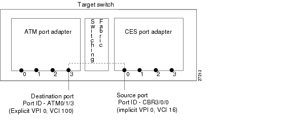
Configuring a Hard PVC for Unstructured CES
A CES module converts CBR traffic into ATM cells for propagation through an ATM network. CBR traffic arriving on a CES module port must first be segmented into ATM cells. This cell stream is then directed to an outgoing ATM or CBR port.
Note
Figure 18-1 displays unstructured circuit emulation services configured on an ATM switch router, using ATM and CES interface modules to create a hard PVC. In this example, the hard permanent virtual channel (PVC) also uses adaptive clocking, and this CES circuit enables bidirectional, unstructured CBR traffic to flow between these two modules.
Figure 18-1 Hard PVC Configured for Unstructured CES
To configure a hard PVC for unstructured CES, follow these steps, beginning in privileged EXEC mode:
Step 1
Switch# show ces status
Displays information about the current CBR interfaces.
Use this command to choose the source CBR port.
Step 2
Switch# show atm status
Displays information about the current ATM interfaces.
Use this command to choose the destination ATM port.
Note
Step 3
Switch# configure terminal
Switch(config)#
At the privileged EXEC prompt, enters global configuration mode.
Step 4
Switch(config)# interface cbr card/subcard/port
Switch(config-if)#
Selects the physical interface to be configured.
Step 5
Switch(config-if)# shutdown
Disables the interface.
Step 6
Switch(config-if)# ces aal1 service {structured | unstructured}
Configures the CES interface AAL1 service type.
Step 7
Switch(config-if)# ces aal1 clock {adaptive | srts | synchronous}
Configures the AAL1 clock mode.
Step 8
Switch(config-if)# ces circuit circuit-id circuit-name name
Configures the CES interface circuit identifier and circuit name.
Note
Step 9
Switch(config-if)# ces pvc circuit-id interface atm card/subcard/port vpi vpi vci vci
Configures the hard PVC to the ATM interface and VPI/VCI.
Note
Step 10
Switch(config-if)# no shutdown
Reenables the interface.
Example
The following example shows how to configure the hard PVC for unstructured CES (shown in Figure 18-1):
CESwitch# show ces statusInterface IF Admin Port Channels inName Status Status Type use------------- -------- --------- ----------- -----------CBR3/0/0 UP UP T1CBR3/0/1 DOWN UP T1CBR3/0/2 DOWN UP T1CBR3/0/3 UP UP T1CESwitch# show atm statusNUMBER OF INSTALLED CONNECTIONS: (P2P=Point to Point, P2MP=Point to MultiPoint,MP2P=Multipoint to Point)Type PVCs SoftPVCs SVCs TVCs PVPs SoftPVPs SVPs TotalP2P 27 2 13 0 0 0 0 42P2MP 0 0 2 0 0 0 0 2MP2P 0 0 0 0 0 0 0 0TOTAL INSTALLED CONNECTIONS = 44PER-INTERFACE STATUS SUMMARY AT 18:12:45 UTC Thu Jul 22 1999:Interface IF Admin Auto-Cfg ILMI Addr SSCOP HelloName Status Status Status Reg State State State------------- -------- ------------ -------- ------------ --------- --------ATM0/0/1 DOWN down waiting n/a Idle n/aATM0/0/5 DOWN shutdown waiting n/a Idle n/aATM0/0/6 DOWN shutdown waiting n/a Idle n/aATM0/0/7 DOWN shutdown waiting n/a Idle n/aATM0/0/ima1 UP up done UpAndNormal Active 2way_inATM0/1/0 DOWN shutdown waiting n/a Idle n/aATM0/1/1 DOWN shutdown waiting n/a Idle n/aATM0/1/2 DOWN shutdown waiting n/a Idle n/aATM0/1/3 DOWN shutdown waiting n/a Idle n/aATM0/1/7 DOWN down waiting n/a Idle n/aATM0/1/ima2 UP up done UpAndNormal Active 2way_inATM1/0/0 DOWN down waiting n/a Idle n/aATM1/0/1 DOWN down waiting n/a Idle n/aATM1/0/2 DOWN down waiting n/a Idle n/aATM1/0/3 UP up done UpAndNormal Active n/aATM1/1/0 UP up done UpAndNormal Active n/aATM1/1/1 DOWN down waiting n/a Idle n/aATM1/1/2 DOWN down waiting n/a Idle n/aATM1/1/3 DOWN down waiting n/a Idle n/aATM2/0/0 UP up n/a UpAndNormal Idle n/aATM-P3/0/3 UP up waiting n/a Idle n/aATM3/1/0 DOWN down waiting n/a Idle n/aATM3/1/1 UP up done UpAndNormal Active 2way_inATM3/1/1.99 UP up done UpAndNormal Active 2way_inATM3/1/2 DOWN down waiting n/a Idle n/aATM3/1/3 DOWN down waiting n/a Idle n/aATM-P4/0/0 UP up waiting n/a Idle n/aCESwitch# configure terminalCESwitch(config)# interface cbr 3/0/0CESwitch(config-if)# shutdownCESwitch(config-if)# ces aal1 service unstructuredCESwitch(config-if)# ces aal1 clock adaptiveCESwitch(config-if)# ces circuit 0 circuit-name CBR-PVC-ACESwitch(config-if)# ces pvc 0 interface atm 0/1/3 vpi 0 vci 100CESwitch(config-if)# no shutdownVerifying a Hard PVC for Unstructured CES
To verify the hard PVC configuration, use the following privileged EXEC commands:
Examples
The following example shows how to display the basic information about the hard PVC shown in Figure 18-1, using the show ces circuit command:
CESwitch# show ces circuitInterface Circuit Circuit-Type X-interface X-vpi X-vci StatusCBR3/0/0 0 HardPVC ATM0/1/3 0 100 UPThe output from this command verifies the source (CBR 3/0/0) and destination (ATM 0/1/3) port IDs of the hard PVC and indicates that the circuit is up.
The following example shows how to display detailed information about the hard PVC shown in Figure 18-1, using the show ces circuit interface command:
CESwitch# show ces circuit interface cbr 3/0/0 0Circuit: Name CBR-PVC-A, Circuit-state ADMIN_UP / oper-state UPInterface CBR3/0/0, Circuit_id 0, Port-Type T1, Port-State UPPort Clocking network-derived, aal1 Clocking Method CESIWF_AAL1_CLOCK_ADAPTChannel in use on this port: 1-24Channels used by this circuit: 1-24Cell-Rate: 4107, Bit-Rate 1544000cas OFF, cell_header 0x100 (vci = 16)Configured CDV 2000 usecs, Measured CDV unavailableDe-jitter: UnderFlow 903952, OverFlow 0ErrTolerance 8, idleCircuitdetect OFF, onHookIdleCode 0x0state: VcAlarm, maxQueueDepth 827, startDequeueDepth 437Partial Fill: 47, Structured Data Transfer 0HardPVCsrc: CBR3/0/0 vpi 0, vci 16Dst: ATM0/1/3 vpi 0, vci 100The output from this command verifies the following configuration information:
•
•
•
•
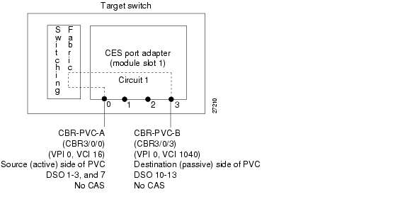
Configuring a Soft PVC for Unstructured CES
In a soft PVC, as well as a hard PVC, you configure both ends of the CES circuit. However, a soft PVC typically involves CES modules at opposite edges of an ATM network, so a soft PVC can be set up between any two CES modules anywhere in your network.
The destination address of a soft PVC can point to either of the following:
•
•
For example, to set up a soft PVC involving a local node and a destination node at the opposite edge of the network, you need to determine the CES-IWF ATM address of the port in the destination node to complete soft PVC setup.
To obtain the destination address (dest-address) for a port already configured in a CES port adapter, log into the remote ATM switch router containing that module. Then use the show ces address command to display all the CES-IWF ATM addresses currently configured for that node.
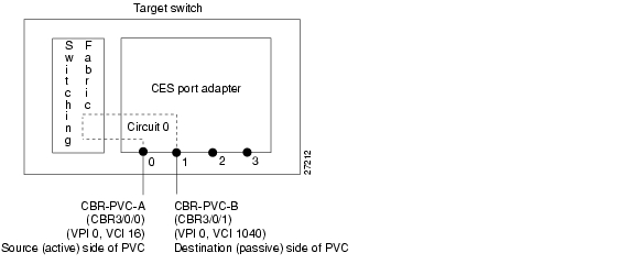
Figure 18-2 displays a soft PVC configured for unstructured CES. The soft PVC uses adaptive clocking and the source clock is network-derived.
Note
Figure 18-2 Soft PVC Configured for Unstructured CES
Configuring a soft PVC for unstructured CES is a two-phase process:
•
•
Phase 1—Configuring the Destination (Passive) Side of the Soft PVC
To configure the destination (passive) side of a soft PVC destination port, follow these steps, beginning in privileged EXEC mode:
Example
The following example shows how to configure the destination (passive) side of a soft PVC, as shown in Figure 18-2:
CESwitch# show ces statusInterface IF Admin Port Channels inName Status Status Type use------------- -------- --------- ----------- -----------CBR3/0/0 UP UP T1CBR3/0/1 UP UP T1CBR3/0/2 UP UP T1CBR3/0/3 UP UP T1CESwitch# configure terminalCESwitch(config)# interface cbr 3/0/1CESwitch(config-if)# shutdownCESwitch(config-if)# ces aal1 service unstructuredCESwitch(config-if)# ces aal1 clock synchronousCESwitch(config-if)# ces dsx1 clock source network-derivedCESwitch(config-if)# ces circuit 0 circuit-name CBR-PVC-BCESwitch(config-if)# no shutdown
Note
Phase 2—Configuring the Source (Active) Side of the Soft PVC
To configure the source (active) side of a soft PVC destination port, follow these steps, beginning in privileged EXEC mode:
Example
The following example shows how to configure the source (active) side of a soft PVC, as shown in Figure 18-2:
CESwitch# show ces addressCES-IWF ATM Address(es):47.0091.8100.0000.0060.5c71.1f01.4000.0c80.1034.10 CBR-PVC-BCESwitch#configure terminalCESwitch(config)#interface cbr 3/0/0CESwitch(config-if)# shutdownCESwitch(config-if)# ces aal1 service unstructuredCESwitch(config-if)# ces aal1 clock synchronousCESwitch(config-if)# ces dsx1 clock source network-derivedCESwitch(config-if)#ces circuit 0 circuit-name CBR-PVC-ACESwitch(config-if)# ces pvc 0 dest-address 47.0091.8100.0000.0060.5c71.1f01.4000.0c80.1034.10 vpi 0 vci 1040CESwitch(config-if)# no shutdownVerifying a Soft PVC for Unstructured CES
To verify the soft PVC configuration, use the following privileged EXEC commands:
Examples
The following example shows how to display the soft PVC configured in the previous section (shown in Figure 18-2), using the show ces circuit command:
CESwitch# show ces circuitInterface Circuit Circuit-Type X-interface X-vpi X-vci StatusCBR3/0/0 0 Active SoftVC ATM-P3/0/3 0 16 UPCBR3/0/1 0 Passive SoftVC ATM-P3/0/3 0 1040 UPThe following example shows how to display the detailed circuit information for CBR 3/0/1, the destination (passive) side of the soft PVC (shown in Figure 18-2), using the show ces circuit interface cbr command:
CESwitch# show ces circuit interface cbr 3/0/1 0Circuit: Name CBR-PVC-B, Circuit-state ADMIN_UP / oper-state UPInterface CBR3/0/1, Circuit_id 0, Port-Type T1, Port-State UPPort Clocking network-derived, aal1 Clocking Method CESIWF_AAL1_CLOCK_SYNCChannel in use on this port: 1-24Channels used by this circuit: 1-24Cell-Rate: 4107, Bit-Rate 1544000cas OFF, cell_header 0xC100 (vci = 3088)Configured CDV 2000 usecs, Measured CDV 2378 usecsDe-jitter: UnderFlow 137, OverFlow 0ErrTolerance 8, idleCircuitdetect OFF, onHookIdleCode 0x0state: VcActive, maxQueueDepth 823, startDequeueDepth 435Partial Fill: 47, Structured Data Transfer 0Passive SoftVCSrc: atm addr 47.0091.8100.0000.00e0.4fac.b401.4000.0c81.803c.10 vpi 0, vci 1040Dst: atm addr 47.0091.8100.0000.00e0.4fac.b401.4000.0c81.8030.00The following example shows how to display the detailed circuit information for CBR 3/0/0, the source (active) side of the soft PVC (shown in Figure 18-2), using the show ces circuit interface cbr command:
CESwitch# show ces circuit interface cbr 3/0/0 0Circuit: Name CBR-PVC-A, Circuit-state ADMIN_UP / oper-state UPInterface CBR3/0/0, Circuit_id 0, Port-Type T1, Port-State UPPort Clocking network-derived, aal1 Clocking Method CESIWF_AAL1_CLOCK_SYNCChannel in use on this port: 1-24Channels used by this circuit: 1-24Cell-Rate: 4107, Bit-Rate 1544000cas OFF, cell_header 0x100 (vci = 16)Configured CDV 2000 usecs, Measured CDV 326 usecsDe-jitter: UnderFlow 1, OverFlow 0ErrTolerance 8, idleCircuitdetect OFF, onHookIdleCode 0x0state: VcAlarm, maxQueueDepth 823, startDequeueDepth 435Partial Fill: 47, Structured Data Transfer 0Active SoftVCSrc: atm addr 47.0091.8100.0000.00e0.4fac.b401.4000.0c81.8030.10 vpi 0, vci 16Dst: atm addr 47.0091.8100.0000.00e0.4fac.b401.4000.0c81.803c.10Configuring T1/E1 Structured (n x 64) Circuit Emulation Services
This section provides an overview of structured (n x 64 Kbps) circuit emulation services and describes how to configure CES modules for structured circuit emulation services.
Overview of Structured Circuit Emulation Services
An important distinction between structured and unstructured circuit emulation services is that structured circuit emulation services allow you to allocate T1/E1 bandwidth. Structured circuit emulation services only use the T1/E1 bandwidth actually required to support the active structured circuit(s) you configure.
For example, configuring a CES module for structured services allows you to define multiple hard PVCs or soft PVCs for any CES T1 or E1 port. In both module types, any bits not available for structured circuit emulation services are used for framing and out-of-band control.
n x 64 refers to a circuit bandwidth (data transmission speed) provided by the aggregation of n x 64-Kbps channels, where n is an integer greater than or equal to 1. The 64-Kbps data rate, or the DS0 channel, is the basic building block of the T carrier systems (T1, T2, and T3).
The T1/E1 structured (n x 64) circuit emulation services enable a CES module to function in the same way as a classic Digital Access and Crossconnect System (DACS) switch.
The Simple Gateway Control Protocol (SGCP) provides similar functionality by controlling structured CES circuits for voice over ATM. For additional information see the "Configuring SGCP" section .
For a detailed description of structured circuit emulation services, refer to the Guide to ATM Technology.
Configuring Network Clocking for Structured CES
Circuit emulation services require that the network clock be configured properly. For structured services, synchronous clocking is required. For instructions on configuring network clocking, see the "Configuring Network Clocking" section on page 3-10. For a discussion of clocking issues and network examples, refer to the network clock synchronization and network clocking for CES topics in the Guide to ATM Technology.
Configuring Synchronous Clocking With an OC-12c Interface Module
When synchronous clocking is being used and propagated via an OC-12c interface module, be sure to use the following configurations:
•
•
Configuring a Hard PVC for Structured CES
This section describes how to configure a hard permanent virtual channel (PVC) for structured circuit emulation services.
Figure 18-3 shows that the hard PVC for structured CES connection is configured with the following parameters:
•
•
•
•
Figure 18-3 Hard PVC Configured for Structured CES
To configure the CES port for structured CES, follow these steps, beginning in privileged EXEC mode:
Example
The following example shows how to configure the hard PVC for structured T1 CES, as shown in Figure 18-3:
CESwitch# show ces statusInterface IF Admin Port Channels inName Status Status Type use------------- -------- --------- ----------- -----------CBR3/0/0 UP UP T1CBR3/0/1 UP UP T1CBR3/0/2 UP UP T1CBR3/0/3 UP UP T1CESwitch#show atm statusNUMBER OF INSTALLED CONNECTIONS: (P2P=Point to Point, P2MP=Point to MultiPoint,MP2P=Multipoint to Point)Type PVCs SoftPVCs SVCs TVCs PVPs SoftPVPs SVPs TotalP2P 27 2 13 0 0 0 0 42P2MP 0 0 2 0 0 0 0 2MP2P 0 0 0 0 0 0 0 0TOTAL INSTALLED CONNECTIONS = 44PER-INTERFACE STATUS SUMMARY AT 18:12:45 UTC Thu Jul 22 1999:Interface IF Admin Auto-Cfg ILMI Addr SSCOP HelloName Status Status Status Reg State State State------------- -------- ------------ -------- ------------ --------- --------ATM0/0/1 DOWN down waiting n/a Idle n/aATM0/0/5 DOWN shutdown waiting n/a Idle n/aATM0/0/6 DOWN shutdown waiting n/a Idle n/aATM0/0/7 DOWN shutdown waiting n/a Idle n/aATM0/1/0 DOWN shutdown waiting n/a Idle n/aATM0/1/1 DOWN shutdown waiting n/a Idle n/aATM0/1/2 DOWN shutdown waiting n/a Idle n/aATM0/1/3 UP up done UpAndNormal Active n/aATM0/1/7 DOWN down waiting n/a Idle n/aATM1/0/0 DOWN down waiting n/a Idle n/aATM1/0/1 DOWN down waiting n/a Idle n/aATM1/0/2 DOWN down waiting n/a Idle n/aATM1/0/3 UP up done UpAndNormal Active n/aATM1/1/0 UP up done UpAndNormal Active n/aATM1/1/1 DOWN down waiting n/a Idle n/aATM1/1/2 DOWN down waiting n/a Idle n/aATM1/1/3 DOWN down waiting n/a Idle n/aATM2/0/0 UP up n/a UpAndNormal Idle n/aATM-P3/0/3 UP up waiting n/a Idle n/aATM3/1/0 DOWN down waiting n/a Idle n/aATM3/1/1 UP up done UpAndNormal Active 2way_inATM3/1/2 DOWN down waiting n/a Idle n/aATM3/1/3 DOWN down waiting n/a Idle n/aATM-P4/0/0 UP up waiting n/a Idle n/aCESwitch#configure terminalCESwitch(config)#interface cbr 3/0/0CESwitch(config-if)# shutdownCESwitch(config-if)#ces aal1 service structuredCESwitch(config-if)#ces dsx1 clock source network-derivedCESwitch(config-if)#ces dsx1 framing esfCESwitch(config-if)#ces dsx1 linecode b8zsCESwitch(config-if)#ces circuit 1 timeslots 1-3,7CESwitch(config-if)#ces circuit 1 circuit-name CBR-PVC-ACESwitch(config-if)#ces pvc 1 interface atm 0/1/3 vpi 0 vci 100CESwitch(config-if)# no shutdown
Note
The virtual path identifier/virtual channel identifier (VPI/VCI) values shown in the example (vpi 0 vci 100) are for demonstration purposes only. The service provider you select gives you a virtual path for your data, but you must decide which VCI number to assign to the circuit.
Verifying a Hard PVC for Structured CES
To verify the hard PVC configured with structured services, use the following privileged EXEC commands:
Examples
The following example shows the details of the hard PVC, shown in Figure 18-3, using the show ces circuit command:
CESwitch# show ces circuitInterface Circuit Circuit-Type X-interface X-vpi X-vci StatusCBR3/0/0 1 HardPVC ATM0/1/3 0 100 UPThe output from this command verifies the source (CBR 3/0/0) and destination (ATM 0/1/3) port IDs of the hard PVC and indicates that the circuit is up.
The following example shows the interface details for port CBR 3/0/0 (shown in Figure 18-3), using the show ces circuit interface cbr command:
CESwitch# show ces circuit interface cbr 3/0/0 1Circuit: Name CBR-PVC-A, Circuit-state ADMIN_UP / oper-state UPInterface CBR3/0/0, Circuit_id 1, Port-Type T1, Port-State UPPort Clocking network-derived, aal1 Clocking Method CESIWF_AAL1_CLOCK_SYNCChannel in use on this port: 1-3, 7Channels used by this circuit: 1-3, 7Cell-Rate: 4107, Bit-Rate 1544000cas OFF, cell_header 0x100 (vci = 16)Configured CDV 2000 usecs, Measured CDV 326 usecsDe-jitter: UnderFlow 1, OverFlow 0ErrTolerance 8, idleCircuitdetect OFF, onHookIdleCode 0x0state: VcAlarm, maxQueueDepth 823, startDequeueDepth 435Partial Fill: 47, Structured Data Transfer 1HardPVCSrc: CBR3/0/0 vpi 0, vci 16Dst: ATM0/1/3 vpi 0, vci 100The output from this command verifies the following configuration information:
•
•
•
•
Configuring a Hard PVC for Structured CES with a Shaped VP Tunnel
A shaped VP tunnel is a VP tunnel that, by default, carries only VCs of the constant bit rate (CBR) service category with a peak cell rate (PCR). However, it is possible to configure a shaped virtual path (VP) tunnel to carry VCs of other service categories. The overall output of the shaped VP tunnel is rate-limited, by hardware, to the PCR of the tunnel.
This section describes how to configure a hard PVC for structured CES with a shaped VP tunnel, which is a two-phase process, as follows:
•
•
For more information about configuring shaped VP tunnels, refer to the "Configuring VP Tunnels" section .
Figure 18-4 shows an example of a how a structured CES circuit can be configured with a shaped VP tunnel.
Figure 18-4 Structured CES Circuit Configured with a Shaped VP Tunnel
Phase 1—Configuring a Shaped VP Tunnel
To configure a shaped VP tunnel, follow these steps, beginning in global configuration mode:
Note
Example
The following example shows how to configure a shaped VP tunnel.
CESwitch#configure terminalCESwitch(config)#atm connection-traffic-table-row index 10 cbr pcr 4000CESwitch(config)#interface atm 0/0/0CESwitch(config-if)#shutdownCESwitch(config-if)#atm pvp 1 shaped rx-cttr 10 tx-cttr 10CESwitch(config-if)#no shutdownCESwitch(config-if)#interface atm 0/0/0.1CESwitch(config-subif)#exitCESwitch(config)#
Note
Phase 2—Configuring a Hard PVC
To configure a hard PVC, follow these steps:
Example
The following example shows how to configure hard PVCs for the shaped VP tunnel.
CESwitch# show ces statusInterface IF Admin Port Channels inName Status Status Type use------------- -------- --------- ----------- -----------CBR3/1/0 UP UP T1CBR3/1/1 UP UP T1CBR3/1/2 UP UP T1CBR3/1/3 UP UP T1CESwitch# show atm statusNUMBER OF INSTALLED CONNECTIONS: (P2P=Point to Point, P2MP=Point to MultiPoint,MP2P=Multipoint to Point)Type PVCs SoftPVCs SVCs TVCs PVPs SoftPVPs SVPs TotalP2P 27 2 13 0 0 0 0 42P2MP 0 0 2 0 0 0 0 2MP2P 0 0 0 0 0 0 0 0TOTAL INSTALLED CONNECTIONS = 44PER-INTERFACE STATUS SUMMARY AT 18:12:45 UTC Thu Jul 22 1999:Interface IF Admin Auto-Cfg ILMI Addr SSCOP HelloName Status Status Status Reg State State State------------- -------- ------------ -------- ------------ --------- --------ATM0/0/1 DOWN down waiting n/a Idle n/aATM0/0/5 DOWN shutdown waiting n/a Idle n/aATM0/0/6 DOWN shutdown waiting n/a Idle n/aATM0/0/7 DOWN shutdown waiting n/a Idle n/aATM0/0/ima1 UP up done UpAndNormal Active 2way_inATM0/1/0 DOWN shutdown waiting n/a Idle n/aATM0/1/1 DOWN shutdown waiting n/a Idle n/aATM0/1/2 DOWN shutdown waiting n/a Idle n/aATM0/1/3 UP up done UpAndNormal Active n/aATM0/1/7 DOWN down waiting n/a Idle n/aATM0/1/ima2 UP up done UpAndNormal Active 2way_inATM1/0/0 DOWN down waiting n/a Idle n/aATM1/0/1 DOWN down waiting n/a Idle n/aATM1/0/2 DOWN down waiting n/a Idle n/aATM1/0/3 UP up done UpAndNormal Active n/aATM1/1/0 UP up done UpAndNormal Active n/aATM1/1/1 DOWN down waiting n/a Idle n/aATM1/1/2 DOWN down waiting n/a Idle n/aATM1/1/3 DOWN down waiting n/a Idle n/aATM2/0/0 UP up n/a UpAndNormal Idle n/aATM-P3/0/3 UP up waiting n/a Idle n/aATM3/1/0 DOWN down waiting n/a Idle n/aATM3/1/1 UP up done UpAndNormal Active 2way_inATM3/1/1.99 UP up done UpAndNormal Active 2way_inATM3/1/2 DOWN down waiting n/a Idle n/aATM3/1/3 DOWN down waiting n/a Idle n/aATM-P4/0/0 UP up waiting n/a Idle n/aCESwitch# configure terminalCESwitch(config)# interface cbr 3/1/0CESwitch(config-if)# shutdownCESwitch(config-if)# ces aal1 service structuredCESwitch(config-if)# ces circuit 1 timeslots 1CESwitch(config-if)# ces pvc 1 interface atm 0/0/0.1 vpi 1 vci 101CESwitch(config-if)# ces circuit 2 timeslots 2CESwitch(config-if)# ces pvc 2 interface atm 0/0/0.1 vpi 1 vci 102CESwitch(config-if)# ces circuit 3 timeslots 3CESwitch(config-if)# ces pvc 3 interface atm 0/0/0.1 vpi 1 vci 103CESwitch(config-if)# no shutdownVerifying a Hard PVC for Structured CES with a Shaped VP Tunnel
To verify the hard PVC configuration, use the following privileged EXEC commands:
Examples
The following example shows how to display the basic information about the hard PVC shown in Figure 18-4, using the show ces circuit command:
CESwitch# show ces circuitInterface Circuit Circuit-Type X-interface X-vpi X-vci StatusCBR3/1/0 1 HardPVC ATM0/0/0.1 1 101 DOWNCBR3/1/0 2 HardPVC ATM0/0/0.1 1 102 DOWNCBR3/1/0 3 HardPVC ATM0/0/0.1 1 103 DOWNCBR3/1/3 0 Active SoftVC UNKNOWN 0 0 DOWNThe following example shows how to display detailed information about the hard PVC shown in Figure 18-4, using the show ces circuit interface command:
CESwitch# show ces circuit interface cbr 3/1/0 1Circuit: Name CBR3/1/0:1, Circuit-state ADMIN_UP / oper-state UP Interface CBR3Port Clocking loop-timed, aal1 Clocking Method CESIWF_AAL1_CLOCK_SYNCChannel in use on this port: 1-3Channels used by this circuit: 1Cell-Rate: 172, Bit-Rate 64000cas OFF, cell_header 0x100 (vci = 16)Configured CDV 2000 usecs, Measured CDV unavailableDe-jitter: UnderFlow unavailable, OverFlow unavaliableErrTolerance 8, idleCircuitdetect OFF, onHookIdleCode 0x0state: VcLoc, maxQueueDepth 81, startDequeueDepth 64Partial Fill: 47, Structured Data Transfer 1HardPVCsrc: CBR3/1/0 vpi 0, vci 16Dst: ATM0/0/0 vpi 1, vci 101The following example shows how to display detailed information about the shaped VP tunnel shown in Figure 18-4, using the show atm vp command:
NewLs1010# show atm vp interface atm 0/0/0 1Interface: ATM0/0/0, Type: oc3suniVPI = 1Status: SHAPED TUNNELTime-since-last-status-change: 13:59:23Connection-type: PVPCast-type: point-to-pointUsage-Parameter-Control (UPC): passWrr weight: 2Number of OAM-configured connections: 0OAM-configuration: disabledOAM-states: Not-applicableThreshold Group: 1, Cells queued: 0Rx cells: 0, Tx cells: 0Tx Clp0:0, Tx Clp1: 0Rx Clp0:0, Rx Clp1: 0Rx Upc Violations:0, Rx cell drops:0Rx Clp0 q full drops:0, Rx Clp1 qthresh drops:0Rx connection-traffic-table-index: 10
Rx scr-clp01: noneRx mcr-clp01: noneRx cdvt: 1024 (from default for interface)Rx mbs: noneTx scr-clp01: noneTx mcr-clp01: noneTx cdvt: noneTx mbs: noneConfiguring a Soft PVC for Structured CES
In a soft PVC, as well as a hard PVC, you configure both ends of the CES circuit. However, a soft PVC typically involves CES modules at opposite edges of an ATM network, so a soft PVC can be set up between any two CES modules anywhere in your network.
The destination address of a soft PVC can point to either of the following:
•
•
For example, to set up a soft PVC involving a local node and a destination node at the opposite edge of the network, you need to determine the CES-IWF ATM address of the port in the destination node to complete a soft PVC setup.
To obtain the destination address for an already configured port in a CES module, log into the remote ATM switch router containing that module. Then use the show ces address command to display all the CES-IWF ATM addresses currently configured for that node.
Note
This section describes how to configure a soft PVC for structured service based on the following assumptions:
•
•
•
–
–
•
•
•
Figure 18-5 shows an example of a soft PVC configured for structured CES.
Figure 18-5 Soft PVC Configured for Structured CES
Configuring a soft PVC for structured CES is a two-phase process:
•
•
Phase 1—Configuring the Destination (Passive) Side of a Soft PVC
To configure a destination (passive) side of a soft PVC for structured CES, follow these steps, beginning in privileged EXEC mode:
Example
The following example shows how to configure the destination (passive) side of a soft PVC for structured T1 CES, as shown in Figure 18-5:
CESwitch# show ces statusInterface IF Admin Port Channels inName Status Status Type use------------- -------- --------- ----------- -----------CBR3/0/0 UP UP T1CBR3/0/1 UP UP T1CBR3/0/2 UP UP T1CBR3/0/3 UP UP T1CESwitch#configure terminalCESwitch(config)#interface cbr 3/0/3CESwitch(config-if)# shutdownCESwitch(config-if)#ces aal1 service structuredCESwitch(config-if)#ces dsx1 clock source network-derivedCESwitch(config-if)#ces dsx1 framing esfCESwitch(config-if)#ces dsx1 linecode b8zsCESwitch(config-if)#ces circuit 1 timeslots 10-13CESwitch(config-if)#ces circuit 1 circuit-name CBR-PVC-BCESwitch(config-if)# no shutdownPhase 2—Configuring the Source (Active) Side of a Soft PVC
To configure the source (active) side of a soft PVC for structured CES, follow these steps, beginning in privileged EXEC mode:
Example
The following example shows how to configure the source (active) side of a soft PVC for structured CES, as shown in Figure 18-5:
CESwitch#show ces addressCES-IWF ATM Address(es):47.0091.8100.0000.00e0.4fac.b401.4000.0c81.803c.10 CBR3/0/3:1 vpi 0 vci 3088CESwitch#configure terminalCESwitch(config)#interface cbr 3/0/0CESwitch(config-if)#shutdownCESwitch(config-if)#ces circuit 1 timeslots 1-3, 7CESwitch(config-if)#ces circuit 1 circuit-name CBR-PVC-ACESwitch(config-if)# ces pvc 1 dest-address 47.0091.8100.0000.0060.5c71.1f01.4000.0c80.1034.10 vpi 0 vci 16CESwitch(config-if)#no shutdownIf you do not specify the circuit name and logical name parameters in the command line, the system automatically assigns a unique default name in the form CBRx/y/z:# for the circuit being configured. For example, the default name for this particular circuit is CBR3/0/0:1. For structured circuit emulation services, the circuit number sequence always begins at 1 for each port in a CES module.
Verifying a Soft PVC for Structured CES
To verify the soft PVC configured with structured CES, use the following EXEC commands:
Examples
The following example shows the details of the CES circuit (shown in Figure 18-5), using the show ces circuit command:
CESwitch# show ces circuitInterface Circuit Circuit-Type X-interface X-vpi X-vci StatusCBR3/0/0 1 Active SoftVC ATM-P3/0/3 0 3088 UPCBR3/0/3 1 Passive SoftVC ATM-P3/0/3 0 16 UPThe following example shows the interface details for the source port (CBR 3/0/0) (shown in Figure 18-5), using the show ces circuit interface cbr command:
CESwitch# show ces circuit interface cbr 3/0/0 1Circuit: Name CBR-PVC-A, Circuit-state ADMIN_UP / oper-state UPInterface CBR3/0/0, Circuit_id 1, Port-Type T1, Port-State UPPort Clocking network-derived, aal1 Clocking Method CESIWF_AAL1_CLOCK_SYNCChannel in use on this port: 1-3,7Channels used by this circuit: 1-3,7Cell-Rate: 698, Bit-Rate 256000cas OFF, cell_header 0x100 (vci = 16)Configured CDV 2000 usecs, Measured CDV unavailableDe-jitter: UnderFlow unavailable, OverFlow unavailableErrTolerance 8, idleCircuitdetect OFF, onHookIdleCode 0x0state: VcActive, maxQueueDepth 45, startDequeueDepth 28Partial Fill: 47, Structured Data Transfer 98Active SoftVCSrc: atm addr 47.0091.8100.0000.00e0.4fac.b401.4000.0c81.8030.10 vpi 0, vci 16Dst: atm addr 47.0091.8100.0000.00e0.4fac.b401.4000.0c81.803c.10The following example shows the interface details for the destination port (CBR 3/0/3) (shown in Figure 18-5), using the show ces circuit interface cbr command:
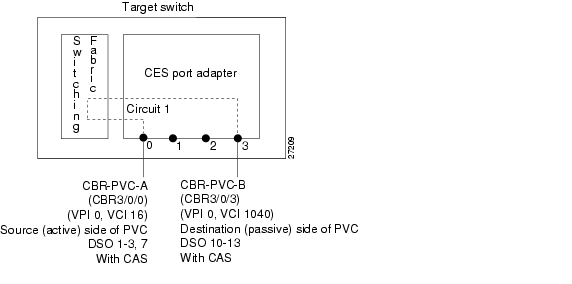
CESwitch# show ces circuit interface cbr 3/0/3 1Circuit: Name CBR-PVC-B, Circuit-state ADMIN_UP / oper-state UPInterface CBR3/0/3, Circuit_id 1, Port-Type T1, Port-State UPPort Clocking network-derived, aal1 Clocking Method CESIWF_AAL1_CLOCK_SYNCChannel in use on this port: 10-13Channels used by this circuit: 10-13Cell-Rate: 698, Bit-Rate 256000cas OFF, cell_header 0xC100 (vci = 3088)Configured CDV 2000 usecs, Measured CDV unavailableDe-jitter: UnderFlow unavailable, OverFlow unavailableErrTolerance 8, idleCircuitdetect OFF, onHookIdleCode 0x0state: VcActive, maxQueueDepth 45, startDequeueDepth 28Partial Fill: 47, Structured Data Transfer 98Passive SoftVCSrc: atm addr 47.0091.8100.0000.00e0.4fac.b401.4000.0c81.803c.10 vpi 0, vci 3088Dst: atm addr 47.0091.8100.0000.00e0.4fac.b401.4000.0c81.8030.00Configuring a Soft PVC for Structured CES with CAS Enabled
Since the CES T1/E1 port adapter emulates CBR services over ATM networks, it must be able to support channel-associated signalling (CAS) information that is introduced into structured CES circuits by PBXs and TDMs. An optional CAS feature for the CES T1/E1 port adapter meets this requirement.
CAS information carried in a CBR bit stream can be configured with a CES module, as follows:
•
•
•
Note
This section describes how to configure a soft PVC for structured CES with channel-associated signalling (CAS) enabled.
Note
The following procedure is based on the following assumptions:
•
•
•
–
–
•
•
Figure 18-6 shows a soft PVC configured for structured CES with CAS enabled.
Figure 18-6 Soft PVC Configured for Structured CES with CAS Enabled
To configure a soft PVC for structured CES with CAS enabled, follow these steps, beginning in privileged EXEC mode:
Example
The following example shows how to enable channel-associated signalling (CAS) on a soft PVC (see Figure 18-6):
CESwitch# show ces statusInterface IF Admin Port Channels inName Status Status Type use------------- -------- --------- ----------- -----------CBR3/0/0 UP UP T1 1-3,7CBR3/0/1 DOWN UP T1CBR3/0/2 DOWN UP T1CBR3/0/3 UP UP T1 10-13CESwitch#configure terminalCESwitch(config)#interface cbr 3/0/0CESwitch(config-if)# shutdownCESwitch(config-if)# ces dsx1 signalmode robbedbitCESwitch(config-if)# ces circuit 1 casCESwitch(config-if)# no shutdownCESwitch(config-if)#exitCESwitch(config)#interface cbr 3/0/3CESwitch(config-if)# shutdownCESwitch(config-if)# ces dsx1 signalmode robbedbitCESwitch(config-if)# ces circuit 1 casCESwitch(config-if)# no shutdownVerifying a Soft PVC for Structured CES with CAS Enabled
To verify the soft PVC with structured CES and CAS enabled, use the following EXEC commands:
Examples
The following example displays the details of the CES circuit (shown in Figure 18-6), using the show ces circuit command at the privileged EXEC mode prompt:
CESwitch# show ces circuitInterface Circuit Circuit-Type X-interface X-vpi X-vci StatusCBR3/0/0 0 Active SoftVC ATM-P3/0/3 0 16 UPCBR3/0/1 0 Passive SoftVC ATM-P3/0/3 0 1040 UPThe following example displays the CAS status for the source port CBR 3/0/0 (shown in Figure 18-6):
CESwitch# show ces circuit interface cbr 3/0/0 1Circuit: Name CBR-PVC-A, Circuit-state ADMIN_UP / oper-state UPInterface CBR3/0/0, Circuit_id 1, Port-Type T1, Port-State UPPort Clocking network-derived, aal1 Clocking Method CESIWF_AAL1_CLOCK_SYNCChannel in use on this port: 1-3,7Channels used by this circuit: 1-3,7Cell-Rate: 698, Bit-Rate 256000Configured CDV 2000 usecs, Measured CDV unavailableDe-jitter: UnderFlow unavailable, OverFlow unavailableErrTolerance 8, idleCircuitdetect OFF, onHookIdleCode 0x0state: VcActive, maxQueueDepth 45, startDequeueDepth 28Partial Fill: 47, Structured Data Transfer 98Active SoftVCSrc: atm addr 47.0091.8100.0000.00e0.4fac.b401.4000.0c81.8030.10 vpi 0, vci 16Dst: atm addr 47.0091.8100.0000.00e0.4fac.b401.4000.0c81.803c.10The following example displays the CAS status for the destination port CBR 3/0/3 (shown in Figure 18-6):
CESwitch# show ces circuit interface cbr 3/0/3 1Circuit: Name CBR-PVC-B, Circuit-state ADMIN_UP / oper-state UPInterface CBR3/0/3, Circuit_id 1, Port-Type T1, Port-State UPPort Clocking network-derived, aal1 Clocking Method CESIWF_AAL1_CLOCK_SYNCChannel in use on this port: 10-13Channels used by this circuit: 10-13Cell-Rate: 698, Bit-Rate 256000Configured CDV 2000 usecs, Measured CDV unavailableDe-jitter: UnderFlow unavailable, OverFlow unavailableErrTolerance 8, idleCircuitdetect OFF, onHookIdleCode 0x0state: VcActive, maxQueueDepth 45, startDequeueDepth 28Partial Fill: 47, Structured Data Transfer 98Passive SoftVCSrc: atm addr 47.0091.8100.0000.00e0.4fac.b401.4000.0c81.803c.10 vpi 0, vci 3088Dst: atm addr 47.0091.8100.0000.00e0.4fac.b401.4000.0c81.8030.00Configuring a Soft PVC for Structured CES with CAS and On-Hook Detection Enabled
This section outlines the additional steps that you must take to activate the on-hook detection (bandwidth-release) feature in a 1 x 64 structured CES circuit.
To configure a soft PVC for structured CES with CAS and on-hook detection enabled, follow these steps, beginning in global configuration mode:
Example
The following example shows how to configure on-hook detection on the soft PVC with structured CES and CAS enabled in the "Configuring a Soft PVC for Structured CES with CAS Enabled" section (shown in Figure 18-6):
CESwitch(config)# interface cbr 3/0/0CESwitch(config-if)# shutdownCESwitch(config-if)# ces circuit 1 cas on-hook-detect 2CESwitch(config-if)# no shutdown
Note
Verifying a Soft PVC for Structured CES with CAS and On-Hook Detection Enabled
To show the on-hook detection configuration of a soft PVC configured with structured CES and CAS enabled, use the following EXEC command:
show ces circuit interface cbr card/subcard/port circuit-id
Shows the detailed interface configuration information for the soft PVC.
Example
The following example shows the soft PVC with CAS and on-hook detection enabled as hexadecimal number 2 (shown in Figure 18-6):
CESwitch# show ces circuit interface cbr 3/0/3 1Circuit: Name CBR-PVC-B, Circuit-state ADMIN_UP / oper-state UPInterface CBR3/0/3, Circuit_id 1, Port-Type T1, Port-State UPPort Clocking network-derived, aal1 Clocking Method CESIWF_AAL1_CLOCK_SYNCChannel in use on this port: 10-13Channels used by this circuit: 10-13Cell-Rate: 698, Bit-Rate 256000Configured CDV 2000 usecs, Measured CDV unavailableDe-jitter: UnderFlow unavailable, OverFlow unavailablestate: VcActive, maxQueueDepth 45, startDequeueDepth 28Partial Fill: 47, Structured Data Transfer 98Passive SoftVCSrc: atm addr 47.0091.8100.0000.00e0.4fac.b401.4000.0c81.803c.10 vpi 0, vci 3088Dst: atm addr 47.0091.8100.0000.00e0.4fac.b401.4000.0c81.8030.00Creating Multiple Structured Soft PVCs on the Same CES Port
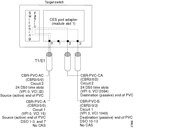
This section describes how to create more than one structured soft permanent virtual channel (soft PVC) on the same CES T1/E1 port. Figure 18-7 shows how you can configure multiple CES circuits on a single T1/E1 port.
Note
Assume that certain configuration information has already been established for a soft PVC (see Figure 18-6) and that you are to create an additional soft PVC involving the same CES module.
The following assumptions apply to creating multiple soft PVCs on the same T1/E1 port (see Figure 18-7):
•
•
•
•
•
•
Figure 18-7 Configuring Multiple Structured Soft PVCs on the Same CES T1/E1 Port
Configuring multiple soft PVCs for structured CES is a two-phase process:
•
•
Phase 1—Configuring the Destination (Passive) Side of Multiple Soft PVCs
To configure multiple soft PVCs on the destination (passive) side of the same port, follow these steps, beginning in global configuration mode:
Example
The following example shows how to configure multiple soft PVCs on the destination (passive) side of the same port (shown in Figure 18-7):
CESwitch(config)# interface cbr 3/0/2CESwitch(config-if)# shutdownCESwitch(config-if)# ces aal1 service structuredCESwitch(config-if)# ces dsx1 clock source network-derivedCESwitch(config-if)# ces dsx1 framing esfCESwitch(config-if)# ces dsx1 linecode b8zsCESwitch(config-if)# ces circuit 2 timeslots 24 circuit-name CBR-PVC-CACESwitch(config-if)# no shutdown
Note
Phase 2—Configuring the Source (Active) Side of Multiple Soft PVCs
To configure multiple soft PVCs on the source (active) side of the same port, follow these steps, beginning in global configuration mode:
Example
The following example shows how to configure multiple soft PVCs on the source (active) side of the same port (shown in Figure 18-7):
CESwitch(config)# interface cbr 3/0/0CESwitch(config-if)# shutdownCESwitch(config-if)# ces circuit 2 timeslots 24CESwitch(config-if)# ces circuit 2 circuit-name CBR-PVC-ACCESwitch(config-if)# no shutdownCESwitch(config-if)# endCESwitch# show ces addressCES-IWF ATM Address(es):47.0091.8100.0000.0060.5c71.1f01.4000.0c80.1030.10 CBR-PVC-A47.0091.8100.0000.0060.5c71.1f01.4000.0c80.1030.20 CBR-PVC-AC47.0091.8100.0000.0060.5c71.1f01.4000.0c80.1034.10 CBR-PVC-B47.0091.8100.0000.0060.5c71.1f01.4000.0c80.1038.10 CBR-PVC-CACESwitch# configure terminalCESwitch(config)# interface cbr 3/0/2CESwitch(config-if)# shutdownCESwitch(config-if)# ces pvc 2 dest-address47.0091.8100.0000.0060.5c71.1f01.4000.0c80.1038.10 vpi 0 vci 2064CESwitch(config-if)# no shutdownIf you do not specify the circuit name and logical name parameters in the command line, the system automatically assigns a unique default name in the form CBRx/y/z:# for the circuit being configured. For example, the default name for this particular circuit is CBR3/0/2:1. For structured circuit emulation services, the circuit number sequence always begins at 1 for each port in a CES module.
Verifying the Creation of Multiple Structured Soft PVCs on the Same CES Port
To verify multiple structured soft PVCs with CAS enabled, use the following EXEC commands:
Examples
The following example displays the circuit details for the soft PVCs that you created in the previous procedure (shown in Figure 18-7) using the show ces circuit command in privileged EXEC mode:
CESwitch# show ces circuitInterface Circuit Circuit-Type X-interface X-vpi X-vci StatusCBR3/0/0 1 Active SoftVC ATM-P3/0/3 0 3088 UPCBR3/0/0 2 Active SoftVC ATM-P3/0/3 0 2080 UPCBR3/0/2 2 Passive SoftVC ATM-P3/0/3 0 32 UPCBR3/0/3 1 Passive SoftVC ATM-P3/0/3 0 16 UPThe following example displays the CES-IWF addresses of the soft PVCs that you configured (shown in Figure 18-7), using the show ces address command in privileged EXEC mode:
CESwitch# show ces addressCES-IWF ATM Address(es):47.0091.8100.0000.00e0.4fac.b401.4000.0c81.8030.10 CBR3/0/0:1 vpi 0 vci 1647.0091.8100.0000.00e0.4fac.b401.4000.0c81.8030.20 CBR3/0/0:2 vpi 0 vci 3247.0091.8100.0000.00e0.4fac.b401.4000.0c81.8038.20 CBR3/0/2:2 vpi 0 vci 208047.0091.8100.0000.00e0.4fac.b401.4000.0c81.803c.10 CBR3/0/3:1 vpi 0 vci 3088The following example displays the interface details for the new circuit 2 soft PVC that you set up on port CBR 3/0/0 (shown in Figure 18-7), using the show ces circuit interface cbr command:
CESwitch# show ces circuit interface cbr 3/0/0 2Circuit: Name CBR-PVC-AC, Circuit-state ADMIN_UP / oper-state UPInterface CBR3/0/0, Circuit_id 2, Port-Type T1, Port-State UPPort Clocking network-derived, aal1 Clocking Method CESIWF_AAL1_CLOCK_SYNCChannel in use on this port: 24Channels used by this circuit: 24Cell-Rate: 172, Bit-Rate 64000cas OFF, cell_header 0x200 (vci = 32)Configured CDV 2000 usecs, Measured CDV unavailableDe-jitter: UnderFlow unavailable, OverFlow unavailableErrTolerance 8, idleCircuitdetect OFF, onHookIdleCode 0x0state: VcActive, maxQueueDepth 81, startDequeueDepth 64Partial Fill: 47, Structured Data Transfer 1Active SoftVCSrc: atm addr 47.0091.8100.0000.00e0.4fac.b401.4000.0c81.8030.20 vpi 0, vci 32Dst: atm addr 47.0091.8100.0000.00e0.4fac.b401.4000.0c81.8038.20The following example displays the interface details for the new circuit 1 soft PVC that you configured on port CBR3/0/2 (shown in Figure 18-7), using the show ces circuit interface cbr command:
CESwitch# show ces circuit interface cbr 3/0/2 2Circuit: Name CBR-PVC-CA, Circuit-state ADMIN_UP / oper-state UPInterface CBR3/0/2, Circuit_id 2, Port-Type T1, Port-State UPPort Clocking network-derived, aal1 Clocking Method CESIWF_AAL1_CLOCK_SYNCChannel in use on this port: 24Channels used by this circuit: 24Cell-Rate: 172, Bit-Rate 64000cas OFF, cell_header 0x8200 (vci = 2080)Configured CDV 2000 usecs, Measured CDV unavailableDe-jitter: UnderFlow unavailable, OverFlow unavailableErrTolerance 8, idleCircuitdetect OFF, onHookIdleCode 0x0state: VcActive, maxQueueDepth 81, startDequeueDepth 64Partial Fill: 47, Structured Data Transfer 1Passive SoftVCSrc: atm addr 47.0091.8100.0000.00e0.4fac.b401.4000.0c81.8038.20 vpi 0, vci 2080Dst: atm addr 47.0091.8100.0000.00e0.4fac.b401.4000.0c81.8030.00Reconfiguring a Previously Established Circuit
Once you have configured a circuit, you cannot change the circuit's configuration while the circuit is up. You must first bring the interface down. Then you can change the circuit configuration. After entering these configuration changes, you must bring the interface back up. To change an enabled circuit's configuration, follow these steps, beginning in global configuration mode:
Note
Examples
The following example disables interface cbr 3/0/0, specifies the clock source as network-derived, changes the AAL1 clocking method to synchronous, and reenables the interface.
CESwitch(config)# interface cbr 3/0/0CESwitch(config-if)# shutdownCESwitch(config-if)# ces dsx1 clock source network-derivedCESwitch(config-if)# ces aal1 clock synchronousCESwitch(config-if)# no shutdownThe following example displays the changed configuration information for the circuit, using the show ces circuit interface cbr command:
CESwitch# show ces circuit interface cbr 3/0/0 0Circuit: Name CBR-PVC-A, Circuit-state ADMIN_UP /Interface CBR3/0/0, Circuit_id 0, Port-Type T1, Port-State UPPort Clocking network-derived, aal1 Clocking Method CESIWF_AAL1_CLOCK_SYNCChannel in use on this port: 1-24Channels used by this circuit: 1-24Cell-Rate: 4107, Bit-Rate 1544000cas OFF, cell_header 0x100 (vci = 16)cdv 2000 usecs, Measured cdv 350 usecsErrTolerance 8, idleCircuitdetect OFF, onHookIdleCode 0x0state: VcAlarm, maxQueueDepth 879, startDequeueDepth 491Partial Fill: 47, Structured Data Transfer 0HardPVCsrc: CBR3/0/0 vpi 0, vci 16Dst: ATM0/1/3 vpi 0, vci 100The output from this command verifies the following configuration information:
•
•
•
Deleting a Previously Established Circuit
This section describes how to delete a previously established circuit.
To delete a previously established circuit, follow these steps, beginning in privileged EXEC mode:
Example
The following example shows how to delete a previously established circuit:
CESwitch# show ces circuitInterface Circuit Circuit-Type X-interface X-vpi X-vci StatusCBR3/0/0 0 HardPVC ATM0/0 0 100 UPCBR3/0/3 0 HardPVC ATM0/0 0 101 UPCESwitch# configure terminalCESwitch(config)# interface cbr 3/0/0CESwitch(config-if)# no ces circuit 0CESwitch(config-if)# exitCESwitch(config)# interface cbr 3/0/3CESwitch(config-if)# no ces circuit 0Verifying Deletion of a Previously Established Circuit
To verify the deletion of a previously configured circuit, use the following privileged EXEC commands:
show ces circuit
Shows the configuration information for the circuit.
show ces address
Shows the configuration information for any CES addresses.
Examples
The following example displays the configuration of any CES circuits:
CESwitch# show ces circuitThe absence of output verifies that all CES circuits are deleted.
The following example displays the configuration of any CES addresses:
CESwitch# show ces addressCES-IWF ATM Address(es):The absence of output verifies that all CES circuits are deleted.
Configuring SGCP
The Simple Gateway Control Protocol (SGCP) controls voice-over-IP gateways by an external call control element (called a call-agent). This has been adapted to allow SGCP to control ATM switch router circuit emulation services (CES) circuits (called endpoints in SGCP). The resulting system (call-agents and gateways) allows for the call-agent to engage in common channel signalling (CCS) over a 64-Kbps CES circuit, governing the interconnection of bearer channels on the CES interface. In this system the ATM switch router acts as a voice-over-ATM gateway.
For overview information about configuring the SCGP feature, refer to the Guide to ATM Technology.
Operation
The network operator can globally enable or disable SGCP operation for the switch. By default, SGCP is disabled. When SGCP is enabled, the ATM switch router begins listening on the well-known User Datagram Protocol (UDP) port for SGCP packets. The endpoint ID in an SGCP packet identifies the CES circuit. The CES circuit endpoint can be used by SGCP if the following conditions exist:
•
•
•
•
•
The following sections describe SGCP configuration tasks:
•
•
•
•
Configuring SGCP on the Entire Switch
To enable SGCP operations for the entire switch, use the following global configuration command:
Example
The following example shows how to enable SGCP for the entire switch:
Switch(config)# sgcpDisplaying SGCP
To display SGCP configuration, operational state, and a summary of connection activity, use the following privileged EXEC command:
Example
The following example displays the SGCP configuration:
Switch# show sgcpSGCP Admin State ACTIVE, Oper State ACTIVESGCP call-agent:none , SGCP graceful-shutdown enabled? FALSESGCP request timeout 2000, SGCP request retries 674 CES endpoint connections created74 CES endpoints in active connectionsConfiguring CES Circuits for SGCP
Any single time slot (64 Kbps) allocated to a circuit on a CES T1/E1 interface can be configured for SGCP with these restrictions:
•
•
Note
When you configure a CES circuit for SGCP, signalling should be given the proper time slot. For T1 CES circuits, a time slot can be given a number from 1 to 24; for E1 CES, a number from 1 to 31.
Although no keyword identifies a CES circuit as allocatable by SGCP, there is normally a simple configuration rule to ensure that signalling allocates the proper time slot:
circuit x is allocated time slot x, 1<=x<=24 (or 31 for E1).
Note
To configure SGCP operation on a CES circuit interface, follow these steps, beginning in global configuration mode:
Example
The following example shows how to configure the CES port for structured CES with all time slots available for SGCP. CES circuit 16 is configured for common channel signalling and specified as a soft permanent virtual channel (soft PVC) to a circuit on the CES port adapter connected to the call-agent.
Switch(config)# interface cbr 1/1/2Switch(config-if)# ces aal1 service structuredSwitch(config-if)# ces circuit 1 timeslot 1Switch(config-if)# ces circuit 2 timeslot 2Switch(config-if)# ces circuit 3 timeslot 3Switch(config-if)# ces circuit 4 timeslot 4Switch(config-if)# ces circuit 5 timeslot 5Switch(config-if)# ces circuit 6 timeslot 6Switch(config-if)# ces circuit 7 timeslot 7Switch(config-if)# ces circuit 8 timeslot 8Switch(config-if)# ces circuit 9 timeslot 9Switch(config-if)# ces circuit 10 timeslot 10Switch(config-if)# ces circuit 11 timeslot 11Switch(config-if)# ces circuit 12 timeslot 12Switch(config-if)# ces circuit 13 timeslot 13Switch(config-if)# ces circuit 14 timeslot 14Switch(config-if)# ces circuit 15 timeslot 15Switch(config-if)# ces circuit 16 timeslot 16Switch(config-if)# ces pvc 16 dest-address47.0091.8100.0000.0060.3e64.fd01.4000.0c80.1038.10 vpi 0 vci 2064Switch(config-if)# ces circuit 17 timeslot 17Switch(config-if)# ces circuit 18 timeslot 18Switch(config-if)# ces circuit 19 timeslot 19Switch(config-if)# ces circuit 20 timeslot 20Switch(config-if)# ces circuit 21 timeslot 21Switch(config-if)# ces circuit 22 timeslot 22Switch(config-if)# ces circuit 23 timeslot 23Switch(config-if)# ces circuit 24 timeslot 24Switch(config-if)# endDisplaying SGCP Endpoints
SGCP endpoints are all the CES circuits that might be eligible for SGCP connections. To display SGCP endpoints, use the following EXEC command:
show sgcp endpoint [interface cbr card/subcard/port [circuit-id]]
Displays the SGCP endpoints.
Note
Example
The following example displays the possible SGCP endpoints on CES interface CBR 1/1/0:
Switch> show sgcp endpoint interface cbr 1/1/0Endpt Timeslots Conn State Call IDCBR1.1.0/1 1 no connectionCBR1.1.0/2 1 no connectionCBR1.1.0/3 1 no connectionCBR1.1.0/4 1 no connectionCBR1.1.0/5 1 no connectionCBR1.1.0/6 1 no connectionCBR1.1.0/7 1 no connectionCBR1.1.0/8 1 no connectionCBR1.1.0/9 1 no connectionCBR1.1.0/10 1 no connectionCBR1.1.0/11 1 activeCBR1.1.0/12 1 no connectionCBR1.1.0/14 1 active 1234abcCBR1.1.0/15 1 active 2234abcCBR1.1.0/16 1 active 3234abcCBR1.1.0/17 1 active 4234abcCBR1.1.0/18 1 active 5234abcCBR1.1.0/19 1 active 6234abcCBR1.1.0/20 1 active 7234abcCBR1.1.0/21 1 active 8234abcCBR1.1.0/22 1 active 9234abcCBR1.1.0/23 1 active a234abcCBR1.1.0/24 1 active b234abcDisplaying SGCP Connections
To display SGCP connections (either globally or per single interface), use the following EXEC command:
show sgcp connection [interface cbr card/subcard/port]
Displays the SGCP connections.
Example
The following example displays all SGCP connections created on the ATM switch router:
Switch> show sgcp connectionConn Endpt Soft VC State Call IdCBR0.0.0/1 Dest- active VC d234abCBR0.0.0/2 Dest- active VC 12345bcCBR0.0.0/3 Dest- active VC 1284abCBR0.0.0/4 Dest- active VC 9234abcConfiguring SGCP Request Handling
When the ATM switch router initiates an SGCP request (for example, to disconnect the circuit), default request timer and request retry values are in operation. To change the default value of SGCP requests, use the global configuration commands, as shown in the following table:
sgcp request timeout msecs
Configures the SGCP request timeout value.
sgcp request retries number
Configures the SGCP request retry value.
Examples
The following example shows how to change the request timeout to 2000 milliseconds:
Switch(config)# sgcp request timeout 2000The following example shows how to change the request retry value to 5:
Switch(config)# sgcp request retries 5Configuring Call-Agent Address
By default the SGCP call agents perform the following tasks:
•
•
To alter this behavior, and send responses and requests to a specific IP address and UDP port, use the following global configuration command:
sgcp call-agent ip-address udp-port
Configures the call-agent IP address and UDP port.
Note
Example
The following example shows how to set the call-agent with IP address 133.20.5.122 and
UDP port 12000:Switch(config)# sgcp call-agent 133.20.5.122 12000Shutting Down SGCP
When SGCP is disabled with the no sgcp command, active SGCP connections are terminated; however DeleteConnection requests are not sent to the call-agent for these active connections.
To notify call-agent and perform a graceful SGCP shutdown, use the following global configuration command:
Example
The following example shows how to perform a graceful shutdown:
Switch(config)# sgcp graceful-shutdown
![]()
![]()
![]()
![]()
![]()
![]()
![]()
![]()
Posted: Mon Oct 11 09:28:43 PDT 2004
All contents are Copyright © 1992--2004 Cisco Systems, Inc. All rights reserved.
Important Notices and Privacy Statement.