|
|

Table Of Contents
Connecting Cisco Analog Video Gateway Network Modules
Information About the EVM-IPVS-16A Network Module
EVM-IPVS-16A Network Module Connectors
EVM-IPVS-16A Network Module LEDs
How to Install, Connect, or Replace the EVM-IPVS-16A Network Module
Installing the EVM-IPVS-16A Network Module in the Router Chassis
Wiring the Terminal Block Connectors
Connecting the EVM-IPVS-16A Network Module to the Network
Performing Online Insertion and Removal of the EVM-IPVS-16A Network Module
Connecting Cisco Analog Video Gateway Network Modules
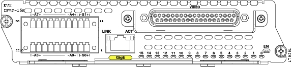
This document provides hardware information about the EVM-IPVS-16A network module, which enables Cisco integrated services routers to capture analog video signals. The EVM-IPVS-16A network module supports up to 16 simultaneous composite video inputs, such as video surveillance cameras. The EVM-IPVS-16A network module also provides alarm input detection, control relay outputs, and RS-485 serial communication interfaces. Figure 39-1 shows the EVM-IPVS-16A network module faceplate.
Figure 39-1 Cisco Analog Video Gateway Network Module (EVM-IPVS-16A) Faceplate
Tip
To determine whether your Cisco router supports a specific network module, see Table 1-6 on page 1-16.
Contents
•
•
Information About the EVM-IPVS-16A Network Module
•
Warning
Warning
Warning
Warning
Note
Note
Note
Video Ports
16 video ports are provided, video ports 0 and 1 can be configured for input or output. The remaining 14 video ports can be configured for input only.
RS-485 Serial Communication Interfaces
The EVM-IPVS-16A network module supports a half-duplex, two-wire RS-485 communication network, which sometimes is called a ring. The EIA/TIA RS-485 communications standard supports up to 32 devices (driver/receiver pairs) on a cable of up to 4,000 feet. The EVM-IPVS-16A network module has two RS-485 ports, supporting up to 64 devices. The EVM-IPVS-16A network module typically acts as the master for each of the two RS-485 networks.
The RS-485 ports can be used to control camera pan, tilt, and zoom (PTZ) functions, as well as other RS-485 devices. Because PTZ camera types use different protocols, the EVM-IPVS-16A network module only supports pass-through mode. In pass-through mode PTZ commands and other data will not be interpreted.
Alarm Inputs and Control Relay Outputs
The EVM-IPVS-16A network module supports eight contact closure interfaces. Interfaces A0, A1, A2, and A3 can be configured as alarm input or relay output, the other interfaces are input only. They are used to detect contact trigger events and control external devices.
In most cases, the contact closure interfaces will be connected to a patch panel through the two terminal block ports on the network module. The patch panel can provide the bias to the circuit.
Caution
Table 39-1 Alarm Input and Output Interface Specifications
Alarm Input Sense Voltage Range
12 V to 24 V
Alarm Output Current Load Range
0 mA to 170 mA
Gigabit Ethernet Port
The external Gigabit Ethernet port is disabled by default. If you enable the Gigabit Ethernet interface, it can act as a routable interface in your network.
EVM-IPVS-16A Network Module Connectors
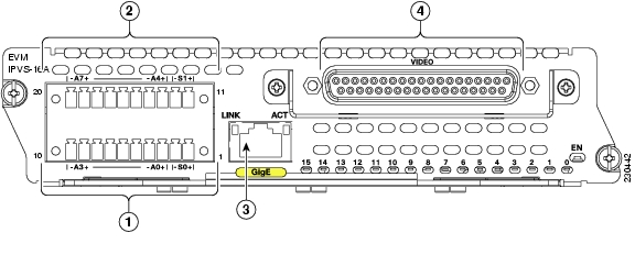
The physical connectors that appear on the EVM-IPVS-16A network module are shown in Figure 39-2 and described in Table 39-2.
Figure 39-2 EVM-IPVS-16A Network Module Connectors
EVM-IPVS-16A Network Module LEDs
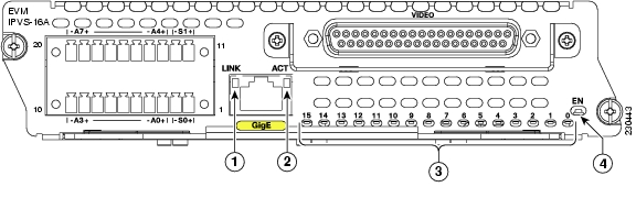
The Cisco analog video gateway network module (EVM-IPVS-16A) has LEDs which denote the status of the network module, shown in Figure 39-3 and described in Table 39-3.
Figure 39-3 EVM-IPVS-16A Network Module LEDs
Table 39-3 EVM-IPVS-16A Network Module LED Descriptions
Ref.1
LINK
Green
Gigabit Ethernet link is up.
Normal indication. No action required.
Off
Gigabit Ethernet link is down.
Check Gigabit Ethernet cable connections.
2
ACT
Amber
Gigabit Ethernet link is actively transmitting or receiving.
Normal indication. No action required.
Off
Gigabit Ethernet link is not actively transmitting or receiving.
Normal indication. No action required.
3
Video signal ports 0-15
Green
There is an active video session for this port, and input video is detected.
Normal indication. No action required.
Amber
There is an active video session for this port, but no input video is detected.
Check the camera is on, then check the video port cable connections.
Off
There is no active video session for this port.
Check the video port cable connections.
See the "Connecting the EVM-IPVS-16A Network Module to the Network" section.
4
EN
On
The router's Cisco IOS software recognizes the network module.
Normal indication. No action required.
Off
The router's Cisco IOS software does not recognize the network module.
Verify that the network module is properly installed in the router chassis. See the " Installing Cisco Network Modules in Cisco Access Routers" chapter.
How to Install, Connect, or Replace the EVM-IPVS-16A Network Module
This section contains the following procedures, each of which may or may not be required, depending on which tasks your service provider performs for you:
•
•
•
Installing the EVM-IPVS-16A Network Module in the Router Chassis
To install the EVM-IPVS-16A network module in the router chassis, see the " Installing Cisco Network Modules in Cisco Access Routers" chapter of the Cisco Network Modules Hardware Installation Guide.
Note
Wiring the Terminal Block Connectors
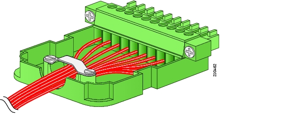
Wire the provided terminal block connectors using the pinout information provided in Table 39-4. (See Figure 39-4.)
Note
Figure 39-4 Wiring the Terminal Block Connectors
Table 39-4 lists each pin on the terminal block, and the corresponding port information.
Tip
Note
Connecting the EVM-IPVS-16A Network Module to the Network
This section describes how to connect the EVM-IPVS-16A network module to devices in the video surveillance network.
Note
Prerequisites
•
•
Steps
To connect the EVM-IPVS-16A network module to the network, follow these steps:
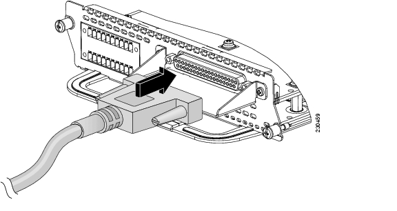
Step 1
Figure 39-5 Connecting the Video Breakout Cable to the EVM-IPVS-16A Network Module
Warning
Step 2
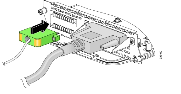
Step 3
Figure 39-6 Connecting the Terminal Block Connectors to the EVM-IPVS-16A Network Module
Step 4
Step 5
What to Do Next
Proceed to the software configuration for your EVM-IPVS-16A network module. See the Configuring the Analog Video Gateway for Integrated Service Routers Cisco IOS feature module.
Performing Online Insertion and Removal of the EVM-IPVS-16A Network Module
The online insertion and removal (OIR) feature enables some Cisco modular access routers to support the replacement of network modules without switching off the router or affecting the operation of other interfaces. Also, routing information is maintained during OIR of network modules.
Note
Restrictions
•
•
•
Steps
To perform OIR of the EVM-IPVS-16A network module in your router, follow these steps:
Step 1
Step 2
Router> enableRouter# configure terminalRouter(config)# interface video-Service-Engine slot/0Router(config-if)# shutRouter(config-if)# shutdownRouter(config-if)# exitStep 3
Warning
Step 4
Step 5
Caution
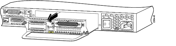
Step 6
Figure 39-7 Removing a Network Module
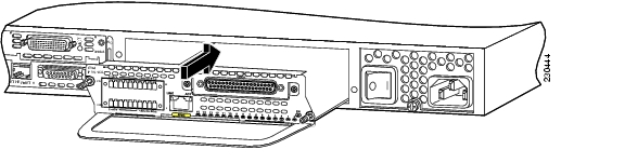
Step 7
Figure 39-8 Installing a Network Module
Step 8
Step 9
Step 10
Step 11
Step 12
Step 13
Step 14
Router> enableRouter# configure terminalRouter(config)# interface video-Service-Engine slot/0Router(config-if)# no shutdownRouter(config-if)# exitRouter# service-module video-Service-Engine slot/0 resetWhat to Do Next
Configure the new EVM-IPVS-16A network module, if changes are necessary. See the Configuring the Analog Video Gateway for Integrated Service Routers Cisco IOS feature module.
Related Documents
Regulatory compliance and safety information
Cisco Network Modules and Interface Cards Regulatory Compliance and Safety Information
Cisco Analog Video Gateway software website and reference documentation
Cisco Network Modules Configuration Guides http://www.cisco.com/en/US/products/hw/modules/ps2797/products_installation_and_configuration_guides_list.html
Cisco Video Management and Storage System software website and reference documentation
Cisco Network Modules Configuration Guides http://www.cisco.com/en/US/products/hw/modules/ps2797/products_installation_and_configuration_guides_list.html
Cisco Video Management and Storage System network module (NME-VMSS) hardware documentation
Cisco Network Modules Install and Upgrade Guides http://www.cisco.com/en/US/products/hw/modules/ps2797/prod_installation_guides_list.html
Cisco product support and technical documentation
Product Support
http://www.cisco.com/web/psa/products/index.htmlTechnical documentation, including feedback and assistance
What's New in Cisco Product Documentation (including monthly listings of new and revised documents) at http://www.cisco.com/en/US/docs/general/whatsnew/whatsnew.html
![]()
![]()
![]()
![]()
![]()
![]()
![]()
![]()
Posted: Fri Dec 14 12:19:28 PST 2007
All contents are Copyright © 1992--2007 Cisco Systems, Inc. All rights reserved.
Important Notices and Privacy Statement.