cc/td/doc/product/access/acs_mod/cis2600/hw_inst/nm_inst
hometocprevnextglossaryfeedbacksearchhelp
PDF

Table Of Contents

Installing Cisco Network Modules in Cisco Access Routers

Recommended Practices for Cisco Network Modules

Safety Recommendations

Preventing Electrostatic Discharge Damage

General Maintenance Guidelines for Cisco Network Modules

Safety Warnings for Cisco Network Modules

Installing Cisco Network Modules in Cisco Access Routers

Tools and Equipment Required During Cisco Network Module Installation

Summary of Installation Tasks

Installing and Removing Blank Faceplates

Preparing Cisco Router Slots for Network Module Installation

Installing Single-Wide, Extended Single-Wide, and Extension Voice Network Modules in Cisco Access Routers

Installing Double-Wide and Extended Double-Wide Network Modules in Cisco Access Routers

Removing or Replacing Cisco Network Modules for Cisco Access Routers

Removing or Replacing Single-Wide, Extended Single-Wide, and Extension Voice Network Modules from Cisco Access Routers

Removing or Replacing Double-Wide and Extended Double-Wide Network Modules in Cisco Access Routers

Replacing Network Modules in Cisco Access Routers with Online Insertion and Removal Support

Removing or Replacing Application and Service Network Modules

Installing Cisco Interface Cards in 1- or 2-Slot Network Modules

Installing Other Accessories on Cisco Network Modules

Installing and Removing GBICs

Where to Go Next


Installing Cisco Network Modules in Cisco Access Routers


This chapter provides information you should know before and during installation of Cisco network modules in Cisco access routers, and contains the following sections:

Recommended Practices for Cisco Network Modules

Installing Cisco Network Modules in Cisco Access Routers

Removing or Replacing Cisco Network Modules for Cisco Access Routers

Installing Cisco Interface Cards in 1- or 2-Slot Network Modules

Installing Other Accessories on Cisco Network Modules

Where to Go Next

Recommended Practices for Cisco Network Modules

This section describes recommended practices for safe and effective installation of the hardware described in this document, and includes the following sections:

Safety Recommendations

Preventing Electrostatic Discharge Damage

General Maintenance Guidelines for Cisco Network Modules

Safety warnings included in this section apply to all Cisco network modules used on Cisco access routers.


Note Recommendations and warnings for specific network modules are documented in the chapter specific to the network module.


Safety Recommendations

To prevent hazardous conditions, follow these safety recommendations while working with this equipment:

Keep tools away from walk areas where you or others could fall over them.

Do not wear loose clothing around the router. Fasten your tie or scarf and roll up your sleeves to prevent clothing from being caught in the chassis.

Wear safety glasses when working under any conditions that might be hazardous to your eyes.

Locate the emergency power-off switch in the room before you start working. If an electrical accident occurs, shut the power off.

Before working on the router, turn off the power and unplug the power cord.

Disconnect all power sources before doing the following:

Installing or removing a router chassis

Working near power supplies

Do not work alone if potentially hazardous conditions exist.

Always check that power is disconnected from a circuit.

Remove possible hazards from your work area, such as damp floors, ungrounded power extension cables, or missing safety grounds.

If an electrical accident occurs, proceed as follows:

Use caution; do not become a victim yourself.

Turn off power to the room using the emergency power-off switch.

If possible, send another person to get medical aid. Otherwise, determine the condition of the victim and then call for help.

Determine if the person needs rescue breathing or external cardiac compressions; then take appropriate action.

Preventing Electrostatic Discharge Damage

Electrostatic discharge can damage equipment and impair electrical circuitry. Electrostatic discharge occurs when electronic printed circuit cards, such as those used in Cisco network modules, are improperly handled and can result in complete or intermittent equipment failure. Always observe the following electrostatic discharge damage (ESD) prevention procedures when installing, removing, and replacing Cisco network modules, Cisco interface cards, Cisco expansion modules, or other electronic printed circuit cards:

Make sure that the router chassis is electrically connected to earth ground.

Wear an ESD-preventive wrist strap, and make sure that it makes good contact with your skin.

Connect the wrist strap clip to an unpainted portion of the chassis frame to channel unwanted ESD voltages to ground.


Caution The wrist strap and clip must be used correctly to ensure proper ESD protection. Periodically confirm that the resistance value of the ESD-preventive wrist strap is between 1 and 10 megohms (Mohm).

If no wrist strap is available, ground yourself by touching the metal part of the router chassis.

General Maintenance Guidelines for Cisco Network Modules

The following maintenance guidelines apply to Cisco network modules:

Keep the router chassis area clear and dust-free during and after installation.

If you remove the chassis cover for any reason, store it in a safe place.

Do not perform any action that creates a hazard to people or makes equipment unsafe.

Keep walk areas clear to prevent falls or damage to equipment.

Follow installation and maintenance procedures as documented by Cisco Systems, Inc.

Safety Warnings for Cisco Network Modules

The following safety warning statements apply to all hardware procedures involving Cisco network modules for Cisco access routers. Translations of these warnings are available in the Cisco Network Modules and Interface Cards Regulatory Compliance and Safety Information document, which ships with all individual Cisco network module orders, and is also available online.


Warning Before working on a chassis or working near power supplies, unplug the power cord on AC units; disconnect the power at the circuit breaker on DC units. Statement 12


Warning Two people are required to lift the chassis. Grasp the chassis underneath the lower edge and lift with both hands. To prevent injury, keep your back straight and lift with your legs, not your back. To prevent damage to the chassis and components, never attempt to lift the chassis with the handles on the power supplies or on the interface processors, or by the plastic panels on the front of the chassis. These handles were not designed to support the weight of the chassis. Statement 194


Warning Only trained and qualified personnel should be allowed to install or replace this equipment. Statement 1030


Warning Ultimate disposal of this product should be handled according to all national laws and regulations. Statement 1040


The following warnings apply in Australia:


Warning Do not touch the power supply when the power cord is connected. For systems with a power switch, line voltages are present within the power supply even when the power switch is OFF and the power cord is connected. For systems without a power switch, line voltages are present within the power supply when the power cord is connected. Statement 4


Warning Before working on equipment that is connected to power lines, remove jewelry (including rings, necklaces, and watches). Metal objects will heat up when connected to power and ground and can cause serious burns or weld the metal object to the terminals. Statement 43


Warning This equipment is to be installed and maintained by service personnel only as defined by AS/NZS 3260 Clause 1.2.14.3 Service Personnel. Statement 88


Warning This equipment will be inoperable when mains power fails. Statement 198


Warning Incorrect connection of this or connected equipment to a general purpose outlet could result in a hazardous situation. Statement 212


Warning Because invisible laser radiation may be emitted from the aperture of the port when no fiber cable is connected, avoid exposure to laser radiation and do not stare into open apertures. Statement 125


Warning Do not work on the system or connect or disconnect cables during periods of lightning activity. Statement 1001


Warning To avoid electric shock, do not connect safety extra-low voltage (SELV) circuits to telephone-network voltage (TNV) circuits. LAN ports contain SELV circuits, and WAN ports contain TNV circuits. Both LAN and WAN ports may use RJ-45 connectors. Use caution when connecting cables. Statement 1021


Warning Hazardous network voltages are present in WAN ports regardless of whether power to the router is OFF or ON. To avoid electric shock, use caution when working near WAN ports. When detaching cables, detach the end away from the router first. Statement 1026


Warning Ultimate disposal of this product should be handled according to all national laws and regulations. Statement 1040


Warning Before opening the chassis, disconnect the telephone-network cables to avoid contact with telephone-network voltages. Statement 1041


Warning The telecommunications lines must be disconnected 1) before unplugging the main power connector and/or 2) while the housing is open. Statement 1043


Installing Cisco Network Modules in Cisco Access Routers

This section describes installation tasks for Cisco network modules used on Cisco access routers, and contains the following subsections:

Tools and Equipment Required During Cisco Network Module Installation

Installing and Removing Blank Faceplates

Installing Blank Faceplates on Cisco Access Routers

Removing Blank Faceplates from Cisco Access Routers

Preparing Cisco Router Slots for Network Module Installation

Installing Slot Dividers

Removing Slot Dividers

Installing Slot Adapters

Removing Slot Adapters

Installing Single-Wide, Extended Single-Wide, and Extension Voice Network Modules in Cisco Access Routers

Installing Double-Wide and Extended Double-Wide Network Modules in Cisco Access Routers


Note The following routers do not support online insertion and removal (OIR) of network modules:

Cisco 2600 series

Cisco 2811

Cisco 2821

Cisco 2851

Cisco 3620

Cisco 3640

Cisco MWR 1941-DC

To avoid damaging the router, turn off electrical power and disconnect network cables before inserting or removing a network module into these routers.


Tools and Equipment Required During Cisco Network Module Installation

You will need the following tools and equipment while working with Cisco network modules:

Number 1 Phillips screwdriver or a small flat-blade screwdriver

ESD-preventive wrist strap

(For routers using DC power) Tape to secure DC circuit breaker handle

Summary of Installation Tasks

When installing a network module in a Cisco access router, perform the following tasks:

Table 2-1 Network Module Hardware Installation Tasks for Cisco Access Routers 

 
For Cisco 2600 Series, Cisco 2811, Cisco 3600 Series (Except Cisco 3660 Routers), and Cisco MWR 1941-DC Routers
For Cisco 2821, Cisco 2851, Cisco 3700 Series, Cisco 3800 Series, and Cisco 3660 Routers

Step 1 

Turn off power to the router.

Turn off power to the router.

Step 2 

Remove blank faceplates from the slots you plan to use. (See the "Removing Blank Faceplates from Cisco Access Routers" section.)

Remove blank faceplates from the slots you plan to use. (See the "Removing Blank Faceplates from Cisco Access Routers" section.)

Step 3 

Install the network module. (See the "Installing Single-Wide, Extended Single-Wide, and Extension Voice Network Modules in Cisco Access Routers" and "Installing Double-Wide and Extended Double-Wide Network Modules in Cisco Access Routers" sections.)

Prepare the slot for the network module form factor you are installing. (See the "Preparing Cisco Router Slots for Network Module Installation" section.)

Step 4 

Install blank faceplates where appropriate. (See the "Installing Blank Faceplates on Cisco Access Routers" section.)

Install the network module. (See the "Installing Single-Wide, Extended Single-Wide, and Extension Voice Network Modules in Cisco Access Routers" section and "Installing Double-Wide and Extended Double-Wide Network Modules in Cisco Access Routers" section sections.)

Step 5 

Install blank faceplates where appropriate. (See the "Installing Blank Faceplates on Cisco Access Routers" section.)

Installing and Removing Blank Faceplates

All empty chassis slots for network modules, extension voice modules, or interface cards must be covered with blank faceplates to ensure proper cooling airflow and to prevent electromagnetic interference.


Note Blank network module faceplates are for single-wide network module slots only.


To install a blank faceplate over a network module slot set up for an extended single-wide, double-wide, or extended double-wide network module, you must prepare the slot for single-wide network modules. See Table 2-3 and Table 2-4 for information on preparing network module slots for different network module form factors.

Table 2-2 Preparing to Install Blank Network Module Faceplates on Cisco Access Router Network Module Slots 

 
On an Extended Single-Wide Slot
On a Double-Wide Slot
On an Extended Double-Wide Slot

Step 1 

Install a slot adapter on the right side of the slot. (See the "Installing Slot Adapters" section.)

Install a slot divider in the slot. (See the "Installing Slot Dividers" section.)

Install a slot divider in the slot. (See the "Installing Slot Dividers" section.)

Step 2 

Install the blank faceplate. (See the "Installing Blank Faceplates on Cisco Access Routers" section.)

Install a slot adapter in the right side of the left slot. (See the "Installing Slot Adapters" section.)

Install slot adapters in the right sides of both slots. (See the "Installing Slot Adapters" section.)

Step 3 

Install one blank faceplate over each slot. (See the "Installing Blank Faceplates on Cisco Access Routers" section.)

Install one blank faceplate over each slot. (See the "Installing Blank Faceplates on Cisco Access Routers" section.)

Installing Blank Faceplates on Cisco Access Routers

To install a blank faceplate, perform the following steps:
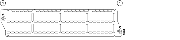

Step 1 Determine which type of blank network module faceplate you are using. (See Figure 2-1 and Figure 2-2.)

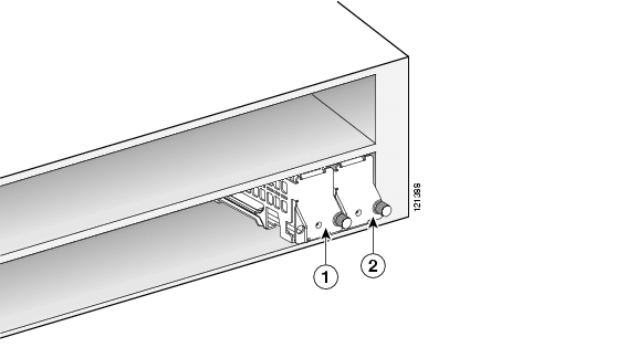
Figure 2-1 Blank Network Module Panel with Screws

1

Captive screws for securing blank faceplate


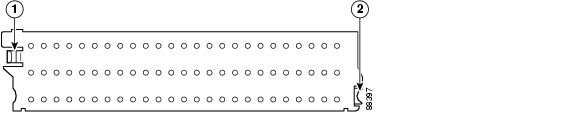
Figure 2-2 Blank Network Module Panel with Tabs

1

Snap-lock tab (use screwdriver to remove)

2

Tab


Step 2 Install the blank faceplate.

(For blank faceplates with mounting screws) Align the captive screws with the screw holes on the chassis. Using either a number 1 Phillips screwdriver or a small flat-blade screwdriver, tighten the captive screws until the blank faceplate is flush with the chassis.

(For blank faceplates with tabs) Align the blank faceplate tabs with the slots on the chassis. Press the blank faceplate against the chassis until the tabs pop into place. The blank faceplate is flush with the chassis when properly installed.

Step 3 Continue with hardware installation tasks.


Removing Blank Faceplates from Cisco Access Routers

To remove blank network module faceplates, perform the following steps:


Step 1 Determine which type of blank network module faceplate you are using. (See Figure 2-1 and Figure 2-2.)

Step 2 Remove the blank faceplate.

(For blank faceplates with mounting screws) Using either a number 1 Phillips screwdriver or a small flat-blade screwdriver, unscrew the captive screws and remove the blank faceplate from the chassis slot you plan to use.

(For blank faceplates with tabs) Using a small flat-blade screwdriver, release the snap-lock tab on the left side of the faceplate (see Figure 2-2). The faceplate pops out when the tab is released.


Tip Save blank faceplates for future use.


Step 3 Continue with hardware installation tasks.


Preparing Cisco Router Slots for Network Module Installation

Several Cisco access routers have flexible network module slots to support all four Cisco network module form factors. Before installing a network module, you must prepare the slot for the network module's particular form factor.

The following Cisco access routers may require network module slot preparation before installation of the network module:

Cisco 2821 and 2851 routers

Cisco 3660 routers (single-wide and double-wide network modules only)

Cisco 3700 series routers (single-wide and double-wide network modules only)

Cisco 3800 series routers


Tip For an introduction to Cisco network module form factors, see the "Introduction to Cisco Network Module Form Factors" section on page 1-1.


To prepare a network module slot for a single-wide or extended single-wide network module, perform the tasks listed in Table 2-3.

Table 2-3 Preparing Network Module Slots for Single-Wide and Extended Single-Wide Network Modules 

 
For Single-Wide Network Modules
For Extended Single-Wide Network Modules

Step 1 

Remove the blank faceplates from the slots you plan to use. (See the "Removing Blank Faceplates from Cisco Access Routers" section.)

Remove the blank faceplates from the slots you plan to use. (See the "Removing Blank Faceplates from Cisco Access Routers" section.)

Step 2 

Remove the slot adapters on the right side of the router slot. (See the "Removing Slot Adapters" section.)

Insert the slot divider. (See the "Installing Slot Dividers" section.)

Step 3 

Insert the slot divider. (See the "Installing Slot Dividers" section.)

Install the network module. (See the "Installing Single-Wide, Extended Single-Wide, and Extension Voice Network Modules in Cisco Access Routers" section.)

Step 4 

(For single-wide network modules only) Insert the slot adapter on the right side of the slot you plan to use. (See the "Installing Slot Adapters" section.)

Step 5 

Install the network module. (See the "Installing Single-Wide, Extended Single-Wide, and Extension Voice Network Modules in Cisco Access Routers" section.)


Tip On Cisco 3800 series routers, extension voice modules can be installed in standard network module slots. When an extension module is installed in a standard network module slot, treat an extension voice module like a single-wide network module.


To prepare a network module slot for a double-wide or extended double-wide network module, perform the tasks listed in Table 2-4.

Table 2-4 Preparing Network Module Slots for Double-Wide and Extended Double-Wide Network Modules 

 
For Double-Wide Network Modules
For Extended Double-Wide Network Modules

Step 1 

Remove blank faceplates from the slots you plan to use. (See the "Removing Blank Faceplates from Cisco Access Routers" section.)

Remove blank faceplates from the slots you plan to use. (See the "Removing Blank Faceplates from Cisco Access Routers" section.)

Step 2 

Remove the slot adapters on the right side of each router slot. (See the "Removing Slot Adapters" section.)

Remove the slot adapter on the right side of the applicable router slot. (See the "Removing Slot Adapters" section.)

Timesaver If the slot adapter is already installed against the right side wall of the router chassis, skip this step.

Step 3 

Remove the slot divider. (See the "Removing Slot Dividers" section.)

Remove the slot divider. (See the "Removing Slot Dividers" section.)

Step 4 

(For double-wide network modules only) Insert 2 slot adapters on the right side of the router slot. (See the "Installing Slot Adapters" section.)

Install the network module. (See the "Installing Single-Wide, Extended Single-Wide, and Extension Voice Network Modules in Cisco Access Routers" section.)

Step 5 

Install the network module. (See the "Installing Single-Wide, Extended Single-Wide, and Extension Voice Network Modules in Cisco Access Routers" section.)

Installing Slot Dividers

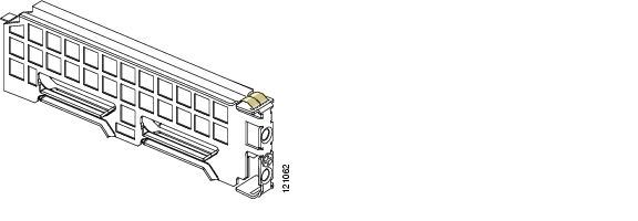
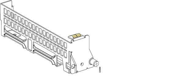
Slot dividers (see Figure 2-3) are used to customize network module slots for different Cisco network module form factors. Slot dividers are used on the following Cisco access routers:

Cisco 2851 routers

Cisco 3660 routers

Cisco 3745 routers

Cisco 3800 series

Slot dividers are installed to permit use of extension voice modules (on Cisco 3800 series routers only), single-wide, and extended single-wide network modules in modular router slots. To determine whether you need to install or remove slot dividers on your Cisco access router, see Table 2-3 and Table 2-4.

Figure 2-3 Slot Divider for Network Module Slots (Sample Shows Divider for Cisco 2851 and 3800 Series)

To install a slot divider, perform the following steps:


Step 1 Remove any installed network modules, blank faceplates, and slot adapters from the router slot you plan to use.

Step 2 Insert the top rails of the slot divider between the two guide rails in the top of the network module slot. (See Figure 2-4.)

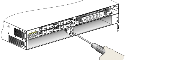
Figure 2-4 Inserting a Slot Divider into a Network Module Slot

Step 3 Push the slot divider in until it is fully seated.

Step 4 Tighten the retention screw on the front of the slot divider with a number 1 Phillips screwdriver. (See Figure 2-5.) When the slot divider is fully inserted, its front surface is flush with the panel of the router. (See Figure 2-5.)

Figure 2-5 Tightening the Slot Divider in a Network Module Slot

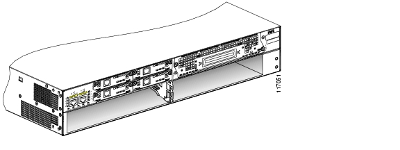
Figure 2-6 Slot Divider Installed in a Network Module Slot

Step 5 Proceed with hardware configuration tasks as listed in Table 2-3 and Table 2-4.


Removing Slot Dividers

Slot dividers are removed to permit use of double-wide and extended double-wide network modules in modular router slots. To determine whether you need to install or remove slot dividers on your Cisco access router, see Table 2-3 and Table 2-4.

To remove slot dividers from network module slots, perform the following steps:


Step 1 Remove any installed network modules, blank faceplates, and slot adapters from the router slot you plan to use.

Step 2 Loosen the retention screw on the front of the slot divider.

Step 3 Pull the slot divider straight out of the network module slot.

Step 4 Proceed with hardware configuration tasks as listed in Table 2-3 and Table 2-4.


Installing Slot Adapters

Slot adapters (see Figure 2-7) are used to customize network module slots for different Cisco network module form factors. Slot adapters are used on the following Cisco access routers:

Cisco 2821

Cisco 2851

Cisco 3800 series

Slot adapters permit installation of extension voice modules (on Cisco 3800 series routers only), single-wide, and extended single-wide network modules in modular router slots.

To determine whether you need to install or remove slot adapters on your Cisco access router, see Table 2-3 and Table 2-4.

Figure 2-7 Sample Slot Adapter for Network Module Slots in Cisco Access Routers

To install a slot adapter, perform the following steps:


Step 1 Remove any installed network modules from the router slot you plan to use.

Step 2 Determine the location for slot adapter installation. (See Figure 2-8 and Figure 2-9.) The extended single-wide network modules use a slot divider instead of a slot adapter. (See Figure 2-6.)

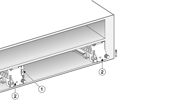
Figure 2-8 Slot Divider and Adapters Locations for Standard Single-Wide Network Modules (Generic Router)

1

Slot divider

2

Slot adapters


Figure 2-9 Slot Adapter Locations for Double-Wide Network Modules (Generic Router)

1

Slot adapter

2

Slot adapter


Step 3 Install other hardware if necessary. (See Table 2-3 and Table 2-4.)

Step 4 Orient the slot adapter so the tab on the rear of the slot adapter aligns with the slot on the router backplane.


Note When correctly aligned, the captive screw on the slot adapter aligns with a threaded hole in the chassis, slot divider, or adjacent slot adapter, depending on your current hardware setup.


Step 5 Slide the slot adapter into the slot.

Step 6 Using a number 1 Phillips or small flat-head screwdriver, tighten the captive screw to secure the slot adapter.


Tip The slot adapter can be secured to the router chassis, to a slot divider, or to another slot adapter, depending on its installation location. See Figure 2-8 for possible variations.


Step 7 Proceed with hardware configuration tasks as listed in Table 2-3 and Table 2-4.


Removing Slot Adapters

Slot adapters are removed to permit use of double-wide and extended double-wide network modules in modular router slots. To determine whether you need to install or remove slot adapters on your Cisco access router, see Table 2-3 and Table 2-4.

To remove slot adapters from network module slots, perform the following steps:


Step 1 Remove any installed network modules and blank faceplates from the router slot you plan to use.

Step 2 Using a number 1 Phillips or small flat-head screwdriver, loosen the captive screw on the slot adapter. (See Figure 2-7.)

Step 3 Slide the slot adapter from the slot.

Step 4 Proceed with hardware configuration tasks as listed in Table 2-3 and Table 2-4.


Installing Single-Wide, Extended Single-Wide, and Extension Voice Network Modules in Cisco Access Routers

Network modules can be installed either before or after mounting the router, whichever is more convenient. To install a network module, follow these steps:


Step 1 Turn off electrical power to the router. Leave the power cable plugged in to channel ESD voltages to ground.

(For the Cisco MWR 1941-DC router) Turn off power by turning the DC power source circuit breaker to OFF. Tape the circuit breaker in the OFF position. To channel ESD voltages to ground, do not remove the wire from the ground lug.


Warning Before performing any of the following procedures, ensure that power is removed from the DC circuit. To ensure that all power is OFF, locate the circuit breaker on the panel board that services the DC circuit, switch the circuit breaker to the OFF position, and tape the switch handle of the circuit breaker in the OFF position. Statement 7


Step 2 Remove all network cables, including telephone cables, from the rear panel of the router.

Step 3 Remove the blank faceplates installed over the slot you intend to use. (See the "Installing and Removing Blank Faceplates" section.)


Tip Save blank faceplates for future use.


Step 4 (For certain Cisco routers) Prepare the slot for the network module form factor you are installing. (See the "Preparing Cisco Router Slots for Network Module Installation" section.)

Step 5 Align the network module with the guides in the chassis walls or slot divider and slide it gently into the slot. (See Figure 2-10.)

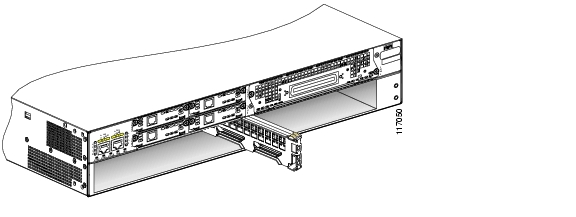
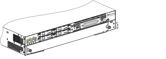
Figure 2-10 Installing Single-Wide and Extended Single-Wide Network Modules in Cisco Access Routers

1

Single-wide network module

2

Router chassis


Step 6 Using the network module handle, push the module into place until you feel the edge connector seat securely into the connector on the router backplane. The network module faceplate should contact the chassis rear panel.

Step 7 Using a number 1 Phillips or flat-blade screwdriver, tighten the captive mounting screws on the module faceplate.

Step 8 Proceed with connecting the network module to the network and power up the router.


Tip See the "Where to Go Next" section for information on locating additional hardware documentation.


Warning After wiring the DC power supply, remove the tape from the circuit breaker switch handle and reinstate power by moving the handle of the circuit breaker to the ON position. Statement 8


Installing Double-Wide and Extended Double-Wide Network Modules in Cisco Access Routers

Network modules can be installed either before or after mounting the router, whichever is more convenient. To install a double-wide or extended double-wide network module, perform these steps:


Step 1 Turn off electrical power to the router. Leave the power cable plugged in to channel ESD voltages to ground.

Step 2 Remove all network cables, including telephone cables, from the rear panel of the router.

Step 3 Remove the blank faceplates installed over the slot you intend to use. (See the "Installing and Removing Blank Faceplates" section.)


Tip Save blank faceplates for future use.


Step 4 (For certain Cisco routers) Prepare the slot for the network module form factor you are installing. (See the "Preparing Cisco Router Slots for Network Module Installation" section.)

Step 5 Confirm that network module levers are in the open position away from the network module faceplate. (See Figure 2-11.)

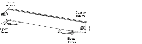
Figure 2-11 Open and Closed Positions for Double-Wide and Extended Double-Wide Network Module Ejector Levers


Timesaver If the network module ejector levers are not in the open position during installation, the network module does not seat properly and connections between the network module and the router backplane are not made. Install the network module with the ejector levers in the open position.


Step 6 Align the network module with the guides in the chassis walls and slide it gently into the slot (see Figure 2-12). Once seated, the ejector levers close halfway.

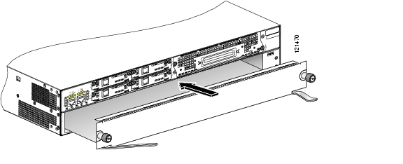
Figure 2-12 Installing Double-Wide and Extended Double-Wide Network Modules in Cisco Access Routers


Caution The double-wide and extended double-wide network modules can be heavy. Avoid touching the network module board to support the module. Handle the network module by the faceplate only to avoid damage to board components.

Step 7 Push the ejector levers so they make contact with the network module faceplate to finish seating the network module and lock the network module into place in the router slot. (See Figure 2-13.)

Figure 2-13 Seating a Double-Wide or Extended Double-Wide Network Module

Step 8 Proceed with connecting the network module to the network and power up the router.


Tip See the "Where to Go Next" section for information on locating additional hardware documentation.


Removing or Replacing Cisco Network Modules for Cisco Access Routers

This section describes removal and replacement procedures for Cisco network modules used in Cisco access routers, and contains the following subsections:

Removing or Replacing Single-Wide, Extended Single-Wide, and Extension Voice Network Modules from Cisco Access Routers

Removing or Replacing Double-Wide and Extended Double-Wide Network Modules in Cisco Access Routers

Replacing Network Modules in Cisco Access Routers with Online Insertion and Removal Support

Removing or Replacing Application and Service Network Modules

Removing or Replacing Single-Wide, Extended Single-Wide, and Extension Voice Network Modules from Cisco Access Routers

To remove or replace a single-wide, extended single-wide, or extension voice network module from a Cisco access router, perform these steps:


Step 1 Turn off power to the router.

(For routers without OIR support) Turn off electrical power to the router. Leave the power cable plugged in to channel ESD voltages to ground.

(For the Cisco MWR 1941-DC router) Turn off power by turning the DC power source circuit breaker to OFF. Tape the circuit breaker in the OFF position. To channel ESD voltages to ground, do not remove the wire from the ground lug.


Warning Before performing any of the following procedures, ensure that power is removed from the DC circuit. To ensure that all power is OFF, locate the circuit breaker on the panel board that services the DC circuit, switch the circuit breaker to the OFF position, and tape the switch handle of the circuit breaker in the OFF position. Statement 7


Step 2 Unplug all network interface cables from the rear panel of the router.


Timesaver To make it easier to work with network cables, label the cables or prepare a network cabling diagram before removing network interface cables from the network module.


Step 3 Using a number 1 Phillips or flat-blade screwdriver, loosen the captive mounting screws on the module faceplate.

Step 4 Using the module handle, pull the network module from the router slot.


Caution To avoid damaging the network module, always handle the network module by the handle or faceplate. Do not touch the circuit board.

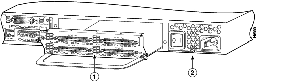
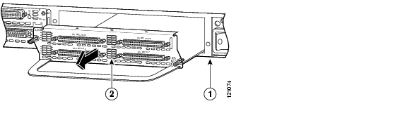
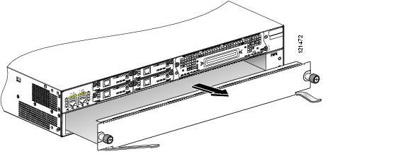
Figure 2-14 Removing Single-Wide and Extended Single-Wide Network Modules from Cisco Access Routers

1

Router chassis

2

Single-wide network module


Step 5 Install the appropriate item.

(If you are replacing the module) Install a replacement module using the procedures described in the "Installing Cisco Network Modules in Cisco Access Routers" section

(If you are not replacing the module) Install a blank faceplate over the empty slots to ensure proper airflow. (See the "Installing and Removing Blank Faceplates" section.)


Tip See the "Where to Go Next" section for information on locating additional hardware documentation.


Removing or Replacing Double-Wide and Extended Double-Wide Network Modules in Cisco Access Routers

To remove or replace a double-wide or extended double-wide network module, perform these steps:


Step 1 Turn off electrical power to the router. Leave the power cable plugged in to channel ESD voltages to ground.

Step 2 Unplug all network interface cables from the network module.


Timesaver To make it easier to work with network cables, label the cables or prepare a network cabling diagram before removing network interface cables from the network module.


Step 3 Using your thumbs, open the levers on the network module faceplate. (See Figure 2-15.) When the ejector levers open, they unseat the network module from the router. The network module faceplate moves away from the router rear panel.

Figure 2-15 Removing Double-Wide and Extended Double-Wide Network Modules from Cisco Access Routers

Step 4 Using your fingers, grasp the edges of the network module faceplate, near the bottom where the board attaches. Pull the network module from the router slot.


Caution The double-wide and extended double-wide network modules can be heavy. Avoid touching the network module board to support the module. Handle the network module by the faceplate only to avoid damage to board components.

Step 5 Install the appropriate item.

(If you are replacing the module) Install a replacement module using the procedures described in the "Installing Cisco Network Modules in Cisco Access Routers" section

(If you are not replacing the module) Install blank faceplates over the empty slot to ensure proper airflow. (See the "Installing and Removing Blank Faceplates" section.)


Tip See the "Where to Go Next" section for information on locating additional hardware documentation.


Replacing Network Modules in Cisco Access Routers with Online Insertion and Removal Support

Online insertion and removal (OIR) provides uninterrupted network operation, maintains routing information, and ensures session preservation. The following Cisco access routers support OIR for similar network modules:

Cisco 3660 routers

Cisco 3745 routers

Cisco 3845 routers


Caution These Cisco access routers support OIR with similar network modules only. If you remove a network module, install the same model network module in its place. For 1- or 2-slot network modules, you must install the same network module and interface card combination.


Caution Do not perform OIR on interface cards in 1- or 2-slot network modules. To avoid damage to the interface card and to the network module, turn off electrical power and disconnect network cables before inserting an interface card into a network module slot.

OIR procedures require some interaction with Cisco IOS software. For more information on Cisco IOS software-related tasks, see documents listed in the "Where to Go Next" section.


Tip Not all Cisco network modules and Cisco interface cards support OIR. Check the hardware documentation specific to your network module or interface card to confirm OIR support before starting OIR procedures.


To replace a network module with OIR support from a Cisco access router, perform the following steps:


Step 1 Initiate a console session with your Cisco access router.

Step 2 Enter interface configuration mode and shut down each interface on the network module you plan to remove. (See Example 2-1.)

Example 2-1 Shutting Down Interfaces on Cisco Network Modules

Router(config)# interface fastethernet 1/0
Router(config-if)# shutdown


Tip To see information for all interfaces available on the network module, use the show interfaces command.


Step 3 Repeat Step 2 for each interface on the network module.

Step 4 Unplug all cables from the network module.


Timesaver To make it easier to work with network cables, label the cables or prepare a network cabling diagram before removing network interface cables from the network module.


Step 5 Remove the network module as described in the "Removing or Replacing Single-Wide, Extended Single-Wide, and Extension Voice Network Modules from Cisco Access Routers" and "Removing or Replacing Double-Wide and Extended Double-Wide Network Modules in Cisco Access Routers" sections.

Step 6 Install a replacement network module. If you are not planning to install another network module at this time, install a blank faceplate over the network module slot. (See the "Installing Blank Faceplates on Cisco Access Routers" section.)

Step 7 Connect the cables removed from the previous network module.

Step 8 Confirm that the network module LEDs come on, and that the Active/Ready LEDs on the front panel of the router also come on. For further information on network module LEDs, see the chapter describing your specific network module.

Step 9 Initiate a console session with your Cisco access router.

Step 10 Enter interface configuration mode and activate each interface on the network module, as shown in Example 2-2.

Example 2-2 Activating Interfaces on Cisco Network Modules

Router(config)# interface fastethernet 1/0
Router(config-if)# no shutdown

Step 11 Repeat Step 10 for every interface on the network module.


Removing or Replacing Application and Service Network Modules

Application and service network modules use hard disks and require special software procedures prior to removal or replacement.


Caution Online removal of disks without proper shutdown can result in file system corruption and might render the disk unusable. The operating system on the applications or services network module must be shut down in an orderly fashion before the network module can be removed.

To perform online removal of a Cisco application and service network module and insertion of a replacement, follow these steps with the router in privileged EXEC mode:


Step 1 Initiate an application and service network module console session using the following command:

Router# service-module service-engine slot/port session

Trying 10.10.10.1, 2129 ... Open

SE-netmodule> enable
Password:
SE-netmodule#

SE-netmodule con now available

Press RETURN to get started!

SE-netmodule> enable
Password:
SE-netmodule#


Timesaver Cisco application and service network modules use a blank password. Press Enter at the password prompt.


Step 2 Save the running configuration for the network module by entering the following command from the SE-netmodule prompt:

SE-netmodule# copy running-config ftp:

Address or name or remote host? username/password/remote host
Destination filename? filename

Step 3 Exit the network module console session by pressing Ctrl-Shift-6, followed by x.

Step 4 On the router, clear the network module console session with the following command:

Router# service-module service-engine slot/port session clear

Step 5 Perform a graceful halt of the network module disk drive with the following command:

Router# service-module service-engine slot/port shutdown

Step 6 Remove the network module, using the procedure described in the "Removing or Replacing Single-Wide, Extended Single-Wide, and Extension Voice Network Modules from Cisco Access Routers" section.

Step 7 Install the replacement network module, using the procedure described in the "Installing Cisco Network Modules in Cisco Access Routers" section.

Step 8 Check that the network module LEDs come on and that the Active/Ready LEDs on the router front panel also come on. This inspection ensures that connections are secure and that the new unit is operational.

Step 9 Initiate a network module console session with the following command:

Router# service-module service-engine slot/port session

Trying 10.10.10.1, 2129 ... Open

SE-netmodule con now available

Press RETURN to get started!

SE-netmodule> enable
SE-netmodule#

Step 10 Restore the running configuration for the network module with the following command from the SE-netmodule prompt:

SE-netmodule# copy ftp: running-config

Address or name or remote host? username/password/remote host
Source filename? filename

Step 11 Exit the network module console session by pressing Ctrl-Shift-6, followed by x.

Step 12 On the router, clear the console session using the following command:

Router# service-module service-engine slot/port session clear


Installing Cisco Interface Cards in 1- or 2-Slot Network Modules

Some network modules have one or two interface card slots, which support a variety of voice and data interface cards. (See Table 1-2 on page 1-8 for more information.)


Note Do not install an ISDN BRI WAN interface card or an ISDN BRI network module in the same chassis as an ISDN PRI network module unless you are using Cisco IOS Release 11.3(3)T or later.


Note Do not install newer BRI WAN interface cards in the same network module as older BRI WAN interface cards. To identify newer BRI WAN interface cards, examine the B-channel LEDs. Newer BRI WAN interface cards have B-channel LEDs that are arranged horizontally. Older BRI WAN interface cards have B-channel LEDs that are arranged vertically.


To install an interface card in a 1- or 2-slot network module, perform the following steps:


Step 1 Turn off electrical power to the router. Leave the power cable plugged in to channel ESD voltages to ground.

The following warning applies to routers that use a DC power supply:


Warning Before performing any of the following procedures, ensure that power is removed from the DC circuit. To ensure that all power is OFF, locate the circuit breaker on the panel board that services the DC circuit, switch the circuit breaker to the OFF position, and tape the switch handle of the circuit breaker in the OFF position. Statement 7


Warning To avoid electric shock, do not insert a WAN or voice interface card into a 2-slot module while power is on or network cables are connected. Statement 68


Caution Do not perform OIR on interface cards in 1- or 2-slot network modules. To avoid damage to the interface card and to the network module, turn off electrical power and disconnect network cables before inserting an interface card into a network module slot.

Step 2 Remove all network cables, including telephone cables, from the rear panel of the router.


Timesaver To make it easier to work with network cables, label the cables or prepare a network cabling diagram before removing network interface cables from the network module.


Step 3 Using a number 1 Phillips or flat-blade screwdriver, loosen the screws on the blank interface card faceplate. (See Figure 2-16.) Remove the blank faceplate.

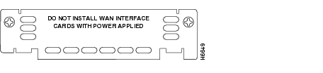
Figure 2-16 Blank Interface Card Faceplate


Tip Save blank interface card faceplates for future use.


Step 4 Align the interface card with the guides in the slot on the network module and slide it gently into place until the edge connector is seated into the connector on the module. (See Figure 2-17.)

Figure 2-17 Installing an Interface Card in a Network Module (Typical)

1

Interface card

2

2-slot network module


Step 5 Using a number 1 Phillips or flat-blade screwdriver, tighten the captive mounting screws into the holes on the network module faceplate.

Step 6 Reinstall the network interface cables and power up the router.

The following warning applies to routers that use a DC power supply:


Warning After wiring the DC power supply, remove the tape from the circuit breaker switch handle and reinstate power by moving the handle of the circuit breaker to the ON position. Statement 8


Installing Other Accessories on Cisco Network Modules

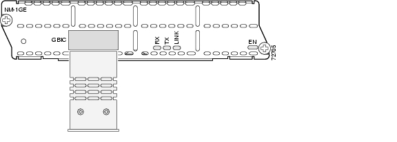
Some Cisco network modules support a variety of additional modules, such as gigabit interface converters (GBICs) and small form-factor pluggable modules (SFPs).

Installing and Removing GBICs

To install a GBIC, perform the following steps:


Warning Because invisible laser radiation may be emitted from the aperture of the port when no fiber cable is connected, avoid exposure to laser radiation and do not stare into open apertures. Statement 125


Step 1 (For optical GBICs) Confirm insertion of plugs into the SC connectors on the GBIC to prevent laser emissions.

Step 2 Hold down the clips on the side of the GBIC while inserting the GBIC into the GBIC slot in the network module faceplate. (See Figure 2-18.)

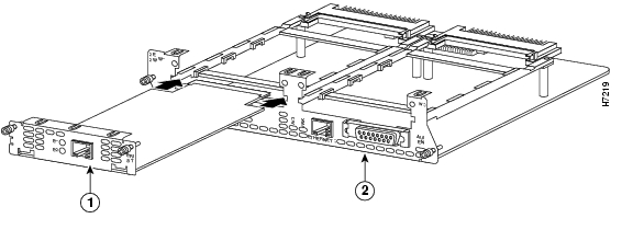
Figure 2-18 Installing a GBIC into a Network Module

Step 3 Release the side clips on the GBIC to lock the GBIC in place.

Step 4 Confirm that the GBIC is seated.


Caution Do not remove the optical port plugs used on the GBIC until you are ready to connect cabling to the network module.

Step 5 (For optical GBICs) Remove the plugs from the SC connectors on the GBIC.


Timesaver If installing the GBIC in a loose network module, install the network module (see the "Installing Cisco Network Modules in Cisco Access Routers" section) before connecting the network module to the network.


To remove a GBIC, perform the following steps:


Warning Because invisible laser radiation may be emitted from the aperture of the port when no fiber cable is connected, avoid exposure to laser radiation and do not stare into open apertures. Statement 125


Step 1 Disconnect the GBIC from the network.

Step 2 (For optical GBICs) Insert plugs into the SC connectors on the GBIC to prevent laser emissions.

Step 3 Hold down the clips on the side of the GBIC and remove the GBIC from the network module.

Step 4 Replace the GBIC with a similar model, or continue with network module removal.


Tip Gigabit Ethernet network modules can be removed with the GBIC installed.


Where to Go Next

For an introduction to Cisco network modules, go to Chapter 1, "Overview of Cisco Network Modules for Cisco Access Routers."

For regulatory compliance and safety information, see the Cisco Network Modules and Interface Cards Regulatory Compliance and Safety Information document.


hometocprevnextglossaryfeedbacksearchhelp

Posted: Fri Dec 14 12:25:02 PST 2007
All contents are Copyright © 1992--2007 Cisco Systems, Inc. All rights reserved.
Important Notices and Privacy Statement.