|
|

Table Of Contents
Connecting 8-Port T1/E1 Network Modules
Safety Warnings for the Cisco T1/E1 Network Module
Cisco T1/E1 Network Module LEDs
Connecting a T1/E1 Network Module to a Network
Connecting 8-Port T1/E1 Network Modules
This chapter describes how to connect 8-port T1/E1 network modules for Cisco integrated service routers. It contains the following sections:
•
Safety Warnings for the Cisco T1/E1 Network Module
•
•
Cisco T1/E1 Network Module
The Cisco T1/E1 network module provides 8 ports of clear channel or channelized T1 and E1 support to Cisco 3800 series integrated services routers:
•
•
T1 support has integrated CSU/DSU capability.
Safety Warnings for the Cisco T1/E1 Network Module
The following safety warnings apply to installation procedures involving the Cisco T1/E1 network module. Translations of these warnings are available in the Cisco Network Modules and Interface Cards Regulatory Compliance and Safety Information document, which is available online.
Warning
Warning
Cisco T1/E1 Network Module LEDs
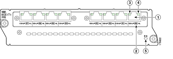
The T1/E1 network module has 2 LEDs for each port that indicate the functionality of the T1 or E1 connection. Figure 38-1 shows the front panel and LEDs. The LEDs are described in Table 38-1.
Figure 38-1 8-Port T1/E1 Network Module Front Panel
CD/LP LEDs are bicolor LEDs with both green and yellow emitters.
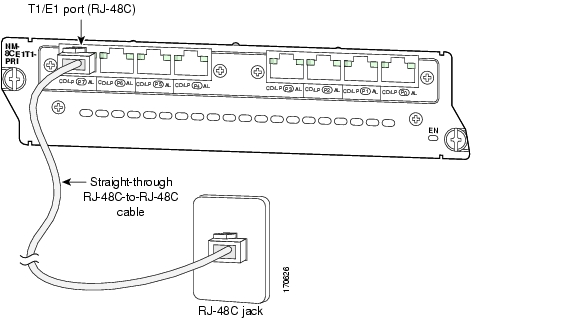
Connecting a T1/E1 Network Module to a Network
Use straight-through RJ-48C-to-RJ-48C cables to connect T1/E1 ports to RJ-48C jacks.
To connect a T1/E1 port to the network, complete the following steps:
Step 1
Step 2
Figure 38-2 Connecting a T1/E1 Port to an RJ-48C Jack
![]()
![]()
![]()
![]()
![]()
![]()
![]()
![]()
Posted: Fri Dec 14 12:14:38 PST 2007
All contents are Copyright © 1992--2007 Cisco Systems, Inc. All rights reserved.
Important Notices and Privacy Statement.