|
|

Table Of Contents
Connecting Cisco High-Density Extension Modules
Cisco High-Density Analog and Digital Extension Module for Voice and Fax
Cisco High-Density Extension Module LEDs and Interfaces
Expansion Modules for Cisco High-Density Extension Modules
Installing Expansion Modules on Cisco High-Density Extension Modules
Connecting Cisco High-Density Extension Modules to the Network
Establishing Emergency or Power-Fail Connections
Cisco High-Density Extension Module Cable Pinouts
Connecting Cisco High-Density Extension Modules
This chapter describes how to connect Cisco high-density extension modules to the network and contains the following sections:
•
Cisco High-Density Analog and Digital Extension Module for Voice and Fax
•
•
•
Tip
Cisco High-Density Analog and Digital Extension Module for Voice and Fax
The Cisco high-density analog and digital extension module for voice and fax is available as an 8-port analog voice module (EVM-HD-8FXS/DID). Each port can be configured in Foreign Exchange Station (FXS) or Direct Inward Dialing (DID) mode through Cisco IOS software commands.
Note
Cisco high-density extension modules provide an integrated high-density analog and digital voice interface for small or medium branch offices. Together with certain expansion modules (see the "Expansion Modules for Cisco High-Density Extension Modules" section), the Cisco high-density extension module provides a maximum of 24 analog voice ports with 8 ports of DID capability.
Note
Caution
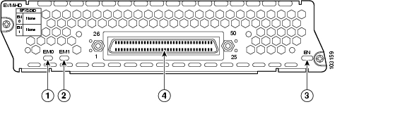
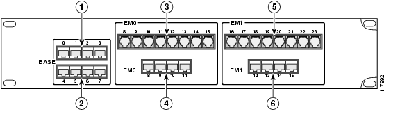
Cisco High-Density Extension Module LEDs and Interfaces
Figure 28-1 shows high-density extension module LEDs and interfaces.
Figure 28-1 Cisco High-Density Extension Module (EVM-HD-8FXS/DID) LEDs
Expansion Modules for Cisco High-Density Extension Modules
The Cisco high-density extension module supports up to two expansion modules (EMs) in the configurations shown in Table 28-1.
The 4-port digital voice/fax expansion module (EM-4BRI-NT/TE) operates as an S/T interface and is capable of NT or TE functionality. In NT mode, the expansion module can supply in-line power for the far end of the connection.
The 7-port analog voice/fax expansion module (EM-HDA-3FXS/4FXO) provides three additional FXS ports and four FXO ports for off-premises analog voice applications.
The 6-port analog voice/fax expansion module (EM-HDA-6FXO) provides six FXO ports for off-premises analog voice applications. The sixth port (port 5) provides a trunk bypass (TBP) or power failover capability.
The 8-port analog voice/fax expansion module (EM-HDA-8FXS) adds an additional eight FXS ports to the Cisco high-density extension module.
Tip
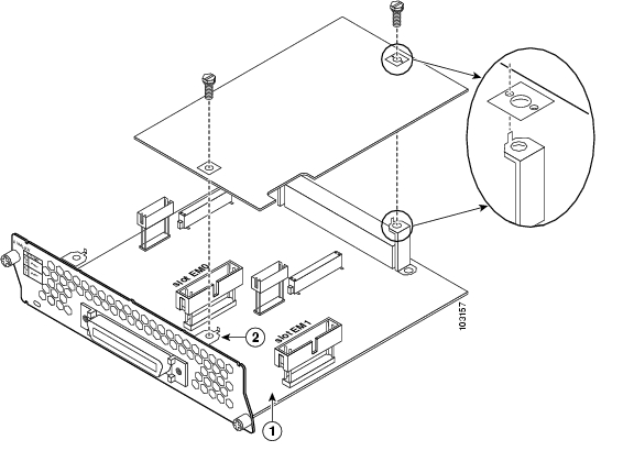
Installing Expansion Modules on Cisco High-Density Extension Modules
Expansion modules can be used to increase the number of ports supported on the high-density extension module.
Note
To install expansion modules, follow these steps:
Step 1
Note
Step 2
Step 3
Tip
Note
Caution
Step 4
Figure 28-2 Installing an Expansion Module on Extension Module Slot EM1
Expansion module connector on the network module (for slot EM1).
Screw bracket on the network module faceplate (for slot EM1).
Step 5
Warning
Tip
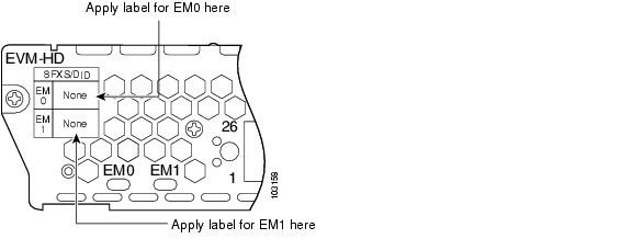
Step 6
Figure 28-3 Label Locations for Expansion Modules on Cisco High-Density Expansion Modules
Step 7
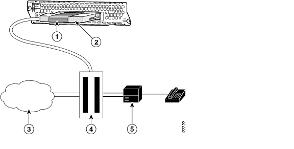
Connecting Cisco High-Density Extension Modules to the Network
The Cisco high-density extension module is connected to a distribution frame or patch panel with an RJ-21 cable. (See Figure 28-4.) RJ-21 cables are not provided with the network module.
Warning
Caution
For ordering information, see the "Obtaining Technical Assistance" section on page xi.
Figure 28-4 Connecting Cisco High-Density Extension Modules (EVM-HD-8FXS/DID) to a Main Distribution Frame or Patch Panel
Strap to secure connector
Main distribution frame
RJ-21 connector
PBX
Public switched telephone network
Distribution panels are generally available from multiple cable and network adapter vendors. Customers may, at their sole discretion, consider using a patch panel from Black Box Corporation (JPM2194A—see Figure 28-5). (Mention of products or services other than Cisco products or services is for information purposes only and constitutes neither an endorsement nor a recommendation.) The Black Box patch panel accommodates RJ-11 and RJ-45 combinations possible on Cisco high-density expansion modules, and offers flexibility for expansion module upgrades (either analog or digital). For ordering information, see the Cisco High-Density Extension Module data sheet.
Figure 28-5 Black Box Patch Panel (JPM2194A) for Use with Cisco High-Density Expansion Modules
Table 28-2 provides pin definitions for the RJ-11 and RJ-45 receptacle types:
Establishing Emergency or Power-Fail Connections
During power failures or when router power is off, emergency voice connections can be made through power-fail ports on the EM-HDA-6FXO expansion module. The expansion module must be properly installed on the Cisco high-density extension module. (See the "Installing Expansion Modules on Cisco High-Density Extension Modules" section.)
To provide an emergency connection, connect an analog phone using the port information listed in Table 28-3.
Note
Caution
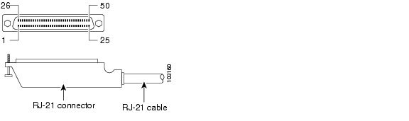
Cisco High-Density Extension Module Cable Pinouts
Figure 28-6 shows the RJ-21 connector wiring for the cable used for the high-density extension module, and Table 28-4 lists cable pinouts. Port usage depends on the type of installed expansion module.
Figure 28-6 Close-Up of the RJ-21 Connector Pinout for Cisco High-Density Extension Modules (EVM-HD-8FXS/DID)
Table 28-4 RJ-21 Connections for the Cisco High-Density Extension Module
26
Base card (EVM-HD-8FXS
Port 0 Tip
—
—
—
—
1
Port 0 Ring
27
Port 1 Tip
2
Port 1 Ring
28
Port 2 Tip
3
Port 2 Ring
29
Port 3 Tip
4
Port 3 Ring
30
Port 4 Tip
5
Port 4 Ring
31
Port 5 Tip
6
Port 5 Ring
32
Port 6 Tip
7
Port 6 Ring
33
Port 7 Tip
8
Port 7 Ring
34
EM0
—
Port 8 Tip
FXS Port 8 Tip
Port 8 Tip
Port x/0 SX-
9
Port 8 Ring
FXS Port 8 Ring
Port 8 Ring
Port x/0 SX+
35
Port 9 Tip
FXS Port 9 Tip
Port 9 Tip
Port x/0 SR-
10
Port 9 Ring
FXS Port 9 Ring
Port 9 Ring
Port x/0 SR+
36
Port 10 Tip
FXS Port 10 Tip
Port 10 Tip
Port x/1 SX-
11
Port 10 Ring
FXS Port 10 Ring
Port 10 Ring
Port x/1 SX+
37
Port 11 Tip
Unused
Port 11 Tip
Port x/1 SR-
12
Port 11 Ring
Unused
Port 11 Ring
Port x/1 SR+
38
Port 12 Tip
FXO Port 12 Tip
Port 12 Tip
Port x/2 SX-
13
Port 12 Ring
FXO Port 12 Ring
Port 12 Ring
Port x/2 SX+
39
Port 13 Tip
FXO Port 13 Tip
Port 13 Tip
Port x/2 SR-
14
Port 13 Ring
FXO Port 13 Ring
Port 13 Ring
Port x/2 SR+
40
Port 14 Tip
FXO Port 14 Tip
Unused
Port x/3 SX-
15
Port 14 Ring
FXO Port 14 Ring
Unused
Port x/3 SX+
41
Port 15 Tip
FXO Port 15 Tip
PFP1 Tip
Port x/3 SR-
16
Port 15 Ring
FXO Port 15 Ring
PFP Ring
Port x/3 SR+
42
EM1
—
Port 16 Tip
FXS Port 16 Tip
Port 16 Tip
Port x/4 SX-
17
Port 16 Ring
FXS Port 16 Ring
Port 16 Ring
Port x/4 SX+
43
Port 17 Tip
FXS Port 17 Tip
Port 17 Tip
Port x/4 SR-
18
Port 17 Ring
FXS Port 17 Ring
Port 17 Ring
Port x/4 SR+
44
Port 18 Tip
FXS Port 18 Tip
Port 18 Tip
Port x/5 SX-
19
Port 18 Ring
FXS Port 18 Ring
Port 18 Ring
Port x/5 SX+
45
Port 19 Tip
Unused
Port 19 Tip
Port x/5 SR-
20
Port 19 Ring
Unused
Port 19 Ring
Port x/5 SR+
46
Port 20 Tip
FXO Port 20 Tip
Port 20 Tip
Port x/6 SX-
21
Port 20 Ring
FXO Port 20 Ring
Port 20 Ring
Port x/6 SX+
47
Port 21 Tip
FXO Port 21 Tip
Port 21 Tip
Port x/6 SR-
22
Port 21 Ring
FXO Port 21 Ring
Port 21 Ring
Port x/6 SR+
48
Port 22 Tip
FXO Port 22 Tip
Unused
Port x/7 SX-
23
Port 22 Ring
FXO Port 22 Ring
Unused
Port x/7 SX+
49
Port 23 Tip
FXO Port 23 Tip
PFP Tip
Port x/7 SR-
24
Port 23 Ring
FXO Port 23 Ring
PFP Ring
Port x/7 SR+
50
Unused
Unused
Unused
Unused
25
Unused
Unused
Unused
Unused
1 During power failures or when router power is off, emergency voice connections can be made through power-fail ports (PFP) on the EM-HDA-6FXO expansion module.
Note
![]()
![]()
![]()
![]()
![]()
![]()
![]()
![]()
Posted: Fri Dec 14 12:25:02 PST 2007
All contents are Copyright © 1992--2007 Cisco Systems, Inc. All rights reserved.
Important Notices and Privacy Statement.