|
|

Table Of Contents
Connecting Alarm Interface Controller Network Modules
Alarm Interface Controller Network Module
Connecting the AIC Network Module to the Network
Connecting Alarm Interface Controller Network Modules
This chapter describes how to install the alarm interface controller (AIC) network module and contains the following sections:
•
Alarm Interface Controller Network Module
•
Tip
Alarm Interface Controller Network Module
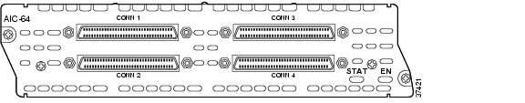
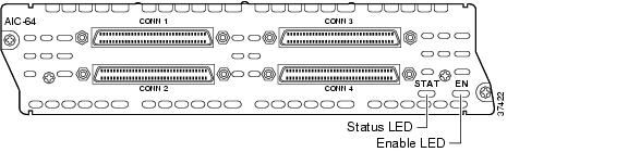
The AIC network module, shown in Figure 29-1, supports 64 alarm inputs. Fifty-six alarm inputs are discrete and can operate on dry contact closure when a patch panel is used. The last eight alarm inputs can be provisioned to accept analog inputs. The AIC network module has 16 control relay outputs.
The AIC network module can be connected to a patch panel. The patch panel provides the bias to the circuit.
The analog alarm inputs can be configured to monitor either DC voltage or current. The AIC can measure voltage from -60 to 60 V or current from 0 to 20 mA. The control relay can be operated to turn an external device on or off. When an event is detected, notification messages are sent to the Operations Support System (OSS) in the network operation center (NOC). These alarm inputs are configured in Cisco IOS software. Some reportable events include:
•
•
•
•
The AIC network module converts relay contact alarm signals to TL1 and SNMP message formats, providing TL1 over TCP/IP and SNMP protocols. All the contact closure-related alarms are routed and reported through the existing OSS and the associated OSS networks. With this network module, the Cisco router sends the TL1 or SNMP messages to the OSS autonomously or in response to TL1 or SNMP commands from the OSS.
The AIC network module is connected to the network using four high-density SCSI-type connectors on the front panel.
Figure 29-1 Alarm Interface Controller Network Module
Connecting the AIC Network Module to the Network
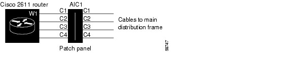
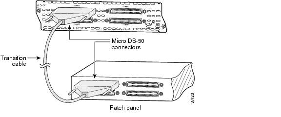
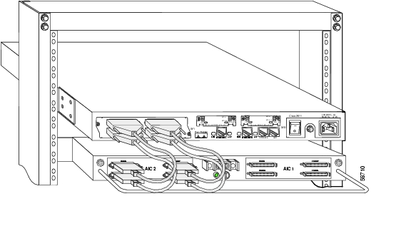
An AIC network module provides four 50-pin receptacles. Use cables that have male Micro DB-50 connectors at both ends with all conductors straight-wired. Central office equipment is cabled to the patch panel, and then cross-connected to the AIC cable.
Two different patch panels can be used. The AIC-1 patch panel terminates one AIC and has voltage terminations with lugs and fuses for voltage monitoring. The AIC-2 patch panel terminates up to two AICs or 128 contact closure points
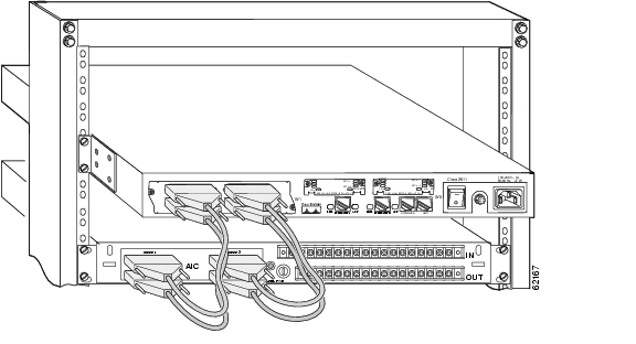
See Figure 29-2 through Figure 29-6 for examples of the AIC connections to the patch panels.
See the AIC data sheet on www.cisco.com for recommended patch panel and cable vendors.
Caution
Caution
Caution
Caution
Ports are numbered from right to left and from bottom to top, as labeled on the module rear panel. Pinouts for the AIC-1 patch panel are shown in Table 29-1. The connector 3 voltage monitor pinouts for AIC-1 are shown in Table 29-2. Pinouts for the AIC-2 patch panel are shown in Table 29-3.
Cables are not provided with the network module. For ordering information, see the "Obtaining Technical Assistance" section on page xi.
Figure 29-2 AIC Network Module Connection Diagram
Figure 29-3 AIC Network Module Faceplate Connections
Figure 29-4 AIC Network Module Connected to AIC-1 Patch Panel
Figure 29-5 AIC Network Module Connected to AIC-2 Patch Panel
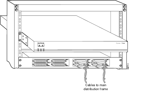
Figure 29-6 AIC-2 Patch Panel Connected to MDF
Table 29-1 AIC-1 Connector Pinouts
1
Alarm Neg1
Alarm Neg 26
Alarm Neg 51
Control Common 1
26
Alarm Pos 1
Alarm Pos 26
Alarm Pos 51
Control N.O. 1
2
Alarm Neg 2
Alarm Neg 27
Alarm Neg 52
Control Common 2
27
Alarm Pos 2
Alarm Pos 27
Alarm Pos 52
Control N.O. 2
3
Alarm Neg 3
Alarm Neg 28
Alarm Neg 53
Control Common 3
28
Alarm Pos 3
Alarm Pos 28
Alarm Pos 53
Control N.O. 3
4
Alarm Neg 4
Alarm Neg 29
Alarm Neg 54
Control Common 4
29
Alarm Pos 4
Alarm Pos 29
Alarm Pos 54
Control N.O. 4
5
Alarm Neg 5
Alarm Neg 30
Alarm Neg 55
Control Common 5
30
Alarm Pos 5
Alarm Pos 30
Alarm Pos 55
Control N.O. 5
6
Alarm Neg 6
Alarm Neg 31
Alarm Neg 56
Control Common 6
31
Alarm Pos 6
Alarm Pos 31
Alarm Pos 56
Control N.O. 6
7
Alarm Neg 7
Alarm Neg 32
See Table 29-2
Control Common 7
32
Alarm Pos 7
Alarm Pos 32
See Table 29-2
Control N.O. 7
8
Alarm Neg 8
Alarm Neg 33
See Table 29-2
Control Common 8
33
Alarm Pos 8
Alarm Pos 33
See Table 29-2
Control N.O. 8
9
Alarm Neg 9
Alarm Neg 34
See Table 29-2
Control Common 9
34
Alarm Pos 9
Alarm Pos 34
See Table 29-2
Control N.O. 9
10
Alarm Neg 10
Alarm Neg 35
See Table 29-2
Control Common 10
35
Alarm Pos 10
Alarm Pos 35
See Table 29-2
Control N.O. 10
11
Alarm Neg 11
Alarm Neg 36
See Table 29-2
Control Common 11
36
Alarm Pos 11
Alarm Pos 36
See Table 29-2
Control N.O. 11
12
Alarm Neg 12
Alarm Neg 37
See Table 29-2
Control Common 12
37
Alarm Pos 12
Alarm Pos 37
See Table 29-2
Control N.O. 12
13
Alarm Neg 13
Alarm Neg 38
See Table 29-2
Control Common 13
38
Alarm Pos 13
Alarm Pos 38
See Table 29-2
Control N.O. 13
14
Alarm Neg 14
Alarm Neg 39
See Table 29-2
Control Common 14
39
Alarm Pos 14
Alarm Pos 39
See Table 29-2
Control N.O. 14
15
Alarm Neg 15
Alarm Neg 40
Not used
Control Common 15
40
Alarm Pos 15
Alarm Pos 40
Not used
Control N.O. 15
16
Alarm Neg 16
Alarm Neg 41
Not used
Control Common 16
41
Alarm Pos 16
Alarm Pos 41
Not used
Control N.O. 16
17
Alarm Neg 17
Alarm Neg 42
Not used
Not used
42
Alarm Pos 17
Alarm Pos 42
Not used
Not used
18
Alarm Neg 18
Alarm Neg 43
Not used
Not used
43
Alarm Pos 18
Alarm Pos 43
Not used
Not used
19
Alarm Neg 19
Alarm Neg 44
Not used
Not used
44
Alarm Pos 19
Alarm Pos 44
Not used
Not used
20
Alarm Neg 20
Alarm Neg 45
Not used
Not used
45
Alarm Pos 20
Alarm Pos 45
Not used
Not used
21
Alarm Neg 21
Alarm Neg 46
Not used
Not used
46
Alarm Pos 21
Alarm Pos 46
Not used
Not used
22
Alarm Neg 22
Alarm Neg 47
Not used
Not used
47
Alarm Pos 22
Alarm Pos 47
Not used
Not used
23
Alarm Neg 23
Alarm Neg 48
Not used
Not used
48
Alarm Pos 23
Alarm Pos 48
Not used
Not used
24
Alarm Neg 24
Alarm Neg 49
Not used
Not used
49
Alarm Pos 24
Alarm Pos 49
Not used
Not used
25
Alarm Neg 25
Alarm Neg 50
Not used
Not used
50
Alarm Pos 25
Alarm Pos 50
Not used
Not used
AIC Network Module LEDs
This section describes AIC network module LEDs. (See Figure 29-7.)
All network modules have an enable (EN) LED. This LED indicates that the module is receiving power from the router chassis.
The AIC network module also has a status (STAT) LED, which is a software-controlled bicolor (green and orange) LED. Both the EN and STAT LEDs turn on when the router is powered up, recycled, or power-cycled, or the AIC is hot-swapped. When the AIC starts to boot up, the STAT LED is initially turned off. It turns green when the software has initialized, has passed POST, and has established communication with IOS.
The STAT LED turns from green to orange when POST has failed or when the software encounters any other fatal fault in its firmware during normal operation.
Table 29-4 defines the state of the card with respect to the states of the LEDs.
Figure 29-7 AIC Network Module LEDs
Table 29-4 AIC LED Description
Off
Off
Off
No power to the AIC
On
Off
Off
Software initializing
On
On
Off
Normal operation
On
Off
On
Fault encountered
![]()
![]()
![]()
![]()
![]()
![]()
![]()
![]()
Posted: Fri Dec 14 12:19:49 PST 2007
All contents are Copyright © 1992--2007 Cisco Systems, Inc. All rights reserved.
Important Notices and Privacy Statement.