|
|

Table Of Contents
Connecting Circuit Emulation Over IP Network Modules
4-Port Serial Interface Network Modules (NM-CEM-4SER)
4-Port Serial Interface Network Module (NM-CEM-4SER) LEDs
Connecting 4-Port Serial Interface Network Modules to the Network
Serial Interface Data Rates and Distance Limitations
Using Cisco 12-in-1 Interface Cables with the 4-Port Serial Interface Network Module (NM-CEM-4SER)
4-Port T1/E1 RJ-48 Interface Network Modules (NM-CEM-4TE1)
4-Port T1/E1 RJ-48 Interface Network Module (NM-CEM-4TE1) LEDs
Connecting 4-Port T1/E1 RJ-48 Interface Network Modules (NM-CEM-4TE1) to the Network
Connecting Circuit Emulation Over IP Network Modules
This chapter describes how to connect circuit emulation over Internet Protocol (CEoIP) network modules and contains the following sections:
•
4-Port Serial Interface Network Modules (NM-CEM-4SER)
•
•
•
Tip
Cisco CEoIP Network Modules
Cisco CEoIP network modules provide a virtual circuit through an IP network (similar to a leased line). Transport of data, regardless of the content or structure of the data stream, is entirely transparent to the destination; bits arriving at one end are delivered unchanged to the destination address.
This chapter provides information on the following two Cisco CEoIP network modules:
•
•
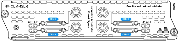
Figure 27-1 4-Port Serial Interface Network Module (NM-CEM-4SER) Faceplate
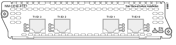
Figure 27-2 4-Port T1/E1 RJ-48 Interface Network Module (NM-CEM-4TE 1) Faceplate
4-Port Serial Interface Network Modules (NM-CEM-4SER)
The 4-port serial interface network module (NM-CEM-4SER) is a single-wide CEoIP network module with four serial ports that support the following interfaces:
•
•
•
•
•
•
Caution
The interface type provided by the port is determined by the cable connected to the port. For information on interface-specific cabling requirements, see the "Connecting 4-Port Serial Interface Network Modules to the Network" section.
For information on network module LEDs, see the "4-Port Serial Interface Network Module (NM-CEM-4SER) LEDs" section.
4-Port Serial Interface Network Module (NM-CEM-4SER) LEDs
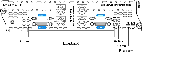
See Figure 27-3 for the location of network module LEDs and Table 27-1 for LED descriptions.
Figure 27-3 4-Port Serial Interface Network Module (NM-CEM-4SER) LEDs
Connecting 4-Port Serial Interface Network Modules to the Network
The 4-port serial interface network module uses Smart Serial connectors, permitting each port to support a basic or extended set of serial control signals, depending on the cable connected to the port.
Caution
The following basic set of control signals is used on Cisco 12-in-1 cables:
•
•
•
•
•
•
The following control signals are part of the extended set, in addition to the basic set listed above, and are used on Cisco Extended 12-in-1 cables:
•
•
•
Note
Note
The 4-port serial interface network module (NM-CEM-4SER) supports both Cisco 12-in-1 interface cables and Cisco Extended 12-in-1 interface cables with user-defined end-connectors permitting connection to either DTE or DCE interfaces.
Interfaces and DTE or DCE modes are defined by the type of cable connected to the network module.
Tip
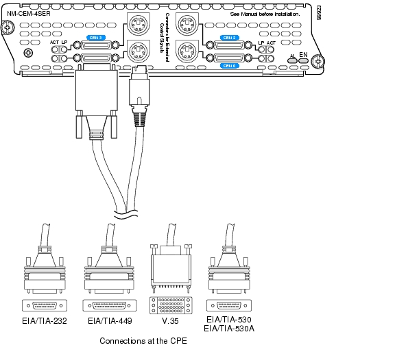
For information on using Cisco 12-in-1 cables with the 4-port serial interface network module, see Table 27-3. Figure 27-4 illustrates how to connect the Cisco 12-in-1 cable to the network module.
For information on using Cisco Extended 12-in-1 cables with the 4-port serial interface network module, see Table 27-4. Figure 27-5 illustrates how to connect the Cisco Extended 12-in-1 cable to the network module.
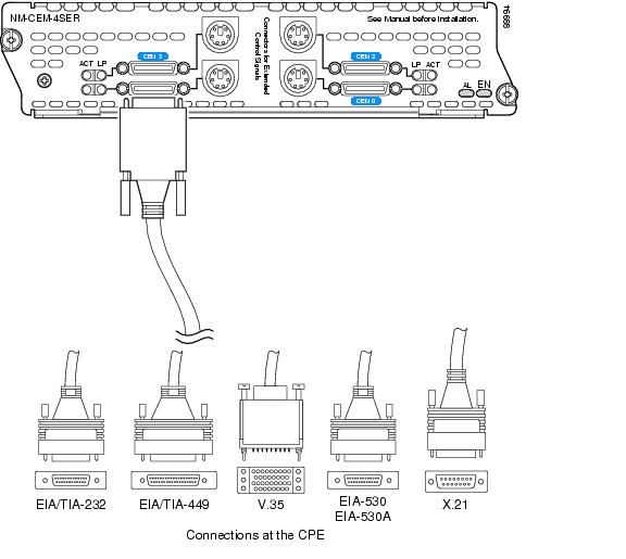
All serial interface types are available in DTE or DCE format: DTE requires a plug connector at the customer premises equipment (CPE) end, and DCE requires a receptacle connector at the CPE end.
Serial Interface Data Rates and Distance Limitations
All serial signals are subject to distance limits, beyond which the signal degrades significantly or is completely lost. Generally, the slower the data rate, the greater the distance the signal can travel.
Table 27-2 lists maximum recommended speeds and distances for each serial interface type. If you understand and compensate for potential electrical problems, you may get good results at speeds and distances greater than those listed. For instance, the recommended maximum rate for V.35 is 2 Mbps, but 4 Mbps is commonly used.
Balanced drivers allow EIA/TIA-449, EIA/TIA-530, EIA/TIA-530A, V.35, and X.21 signals to travel greater distances than EIA/TIA-232 signals. All balanced interfaces easily support 4 to 8 Mbps.
Using Cisco 12-in-1 Interface Cables with the 4-Port Serial Interface Network Module (NM-CEM-4SER)
Table 27-3 lists the Cisco 12-in-1 interface cables supported by the 4-port serial interface network module. Use the cable part number to order replacement or spare cables for the interface and DTE or DCE mode appropriate for your network.
Figure 27-4 illustrates how to connect the Cisco 12-in-1 cable to the network module.
Figure 27-4 Connecting the Cisco 12-in-1 Interface Cable to the 4-Port Serial Interface Network Module (NM-CEM-4SER)
Using Cisco Extended 12-in-1 Interface Cables with the 4-Port Serial Interface Network Module (NM-CEM-4SER)
Table 27-4 lists the Cisco Extended 12-in-1 interface cables supported by the 4-port serial interface network module. Use the cable part number to order replacement or spare cables for the interface and DTE or DCE mode appropriate for your network.
Figure 27-5 illustrates how to connect the Cisco 12-in-1 cable to the network module.
Note
Figure 27-5 Connecting the Cisco Extended 12-in-1 Interface Cable to the 4-Port Serial Interface Network Module (NM-CEM-4SER)
4-Port T1/E1 RJ-48 Interface Network Modules (NM-CEM-4TE1)
The 4-port T1/E1 RJ-48 interface network module (NM-CEM-4TE1) is a single-wide CEoIP network module with four T1/E1 ports. (See Figure 27-2.) The NM-CEM-4TE1 connects to any T1/E1 interface for voice or data.
4-Port T1/E1 RJ-48 Interface Network Module (NM-CEM-4TE1) LEDs
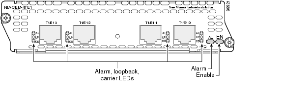
See Figure 27-6 for the location of network module LEDs and Table 27-5 for LED descriptions.
Figure 27-6 4-Port T1/E1 RJ-48 Interface Network Module (NM-CEM-4TE1) LEDs
Connecting 4-Port T1/E1 RJ-48 Interface Network Modules (NM-CEM-4TE1) to the Network
The 4-port T1/E1 RJ-48 interface network module (NM-CEM-4TE1) uses a RJ-48 straight-through cable to connect to the customer premises equipment (CPE) for use in T1 or E1 circuit emulation. (See Figure 27-7.)
Note
When configured for E1 operation, the NM-CEM-4TE1 network module provides four 120-ohm balanced ports. To connect any of these ports to a 75-ohm unbalanced network, use Cisco cable CAB-ADP-75-120. For more information, see the Installing the 75-120-Ohm Adapter Cable on E1 Multichannel Port Adapters document.
Figure 27-7 Connecting the 4-Port T1/E1 RJ-48 Interface Network Module (NM-CEM-4TE1) to the Network
![]()
![]()
![]()
![]()
![]()
![]()
![]()
![]()
Posted: Fri Dec 14 11:53:21 PST 2007
All contents are Copyright © 1992--2007 Cisco Systems, Inc. All rights reserved.
Important Notices and Privacy Statement.