|
|

Table Of Contents
Connecting Voice Network Modules
2- and 4-Channel Voice Network Modules
4-, 8-, and 48-Channel High-Density Voice Network Modules
60-Channel High-Density Voice Network Module
IP Communications High-Density Digital Voice or Fax Network Module
Packet Fax or Voice DSP Modules
Configuring E1 Ports for Normal or Wetting Current Mode
Connecting Voice Network Modules
The voice functionality built into Cisco IOS software enables modular access routers to carry voice traffic, such as telephone calls and faxes, as Voice over IP (VoIP) simultaneously with data traffic over LANs, MANs, and WANs. Voice network modules convert telephone voice signals into a form that can be transmitted over an IP network.
Voice network modules convert telephone voice signals into a form that can be transmitted over an IP network. These modules have one or two slots for installing supported interface cards (see Table 1-1 on page 1-5 and Table 1-2 on page 1-8). Voice interface cards (VICs) or voice/WAN interface cards (VWICs) installed in the voice network module provide physical connections to the telephony equipment or network, and are connected using the appropriate cables. See the Cisco Interface Cards Hardware Installation Guide for more information.
You can install one voice interface card in a 1-slot voice network module, and two voice interface cards in a 2-slot module. For information on installing voice interface cards into a network module, see the "Installing Cisco Interface Cards in 1- or 2-Slot Network Modules" section on page 2-24.
This chapter contains the following sections:
•
2- and 4-Channel Voice Network Modules
•
•
•
Tip
2- and 4-Channel Voice Network Modules
This section describes the following modules:
•
•
For information on the Cisco interface cards supported on these voice network modules, see Table 1-2 on page 1-8.
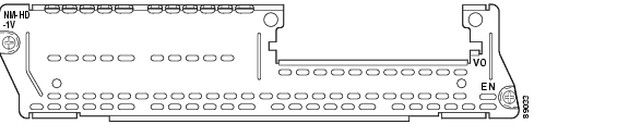
Figure 8-1 1-Slot 2-Channel Voice Network Module (NM-1V)
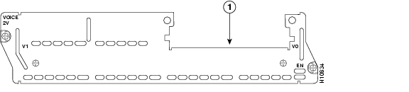
Figure 8-2 2-Slot 4-Channel Voice Network Module (NM-2V)
4-, 8-, and 48-Channel High-Density Voice Network Modules
This section describes the following modules:
•
•
•
Caution
Note
Note
For information on the Cisco interface cards supported on these voice network modules, see Table 1-2 on page 1-8.
Figure 8-3 1-Slot 4-Channel High-Density Network Module (NM-HD-1V)
Figure 8-4 2-Slot 8-Channel High-Density Voice Network Module (NM-HD-2V)
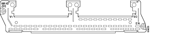
Figure 8-5 2-Slot 48-Channel High-Density Voice Network Module (NM-HD-2VE)
60-Channel High-Density Voice Network Module
This section describes the 60-channel high-density voice (HDV) network module, shown in Figure 8-6. When used in conjunction with T1/E1 multiflex trunk interface cards and packet voice digital signal processor modules (PVDMs), this module is also called a digital T1/E1 packet voice trunk network module.
Figure 8-6 60-Channel High-Density Voice Network Module (NM-HDV)
The 60-channel HDV network module converts voice and fax into IP packets or frames that can be transmitted as VoIP over a variety of transport technologies (channelized T1/E1, Frame Relay, Asynchronous Transfer Mode (ATM), and others). The number of channels supported depends on the number of PVDMs installed:
•
•
Both a 60-channel HDV network module and a voice interface card (VIC) are required to connect to the public switched telephone network (PSTN) or a PBX. One VIC (providing one or two T1/E1 line interfaces) can be installed in the HDV network module. Currently, only the 1- and 2-port T1/E1 multiflex trunk interface cards (VWIC-1MFT-T1, VWIC-2MFT-T1, and VWIC-2MFT-T1-DI) are supported using channel-associated signaling (CAS). In Cisco 3620 and Cisco 3640 routers, at least one other network module or WAN interface card (WIC) must be installed in the router to provide the connection to the IP LAN or WAN. In Cisco 3660 routers, a network module is required for WAN access or a direct connection is required for LAN access. In Cisco 2600 series routers, a WIC is required for WAN access or a direct connection is required for LAN access.
Packet Voice DSP Modules
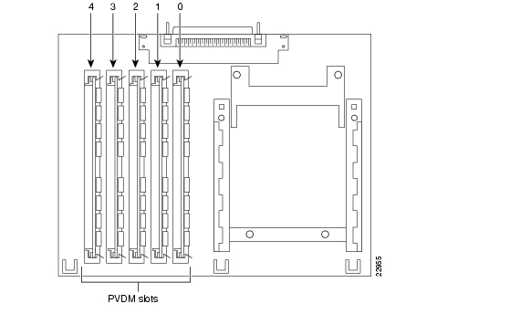
The HDV network module contains five 72-pin SIMM sockets or banks for packet voice DSP modules (PVDMs), numbered 0 through 4. (See Figure 8-7.) Each socket can be filled with a single 72-pin PVDM. The PVDMs must be installed starting from slot 0.
Note
Figure 8-7 PVDM Slot Locations
PVDM Orientation
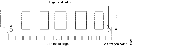
PVDMs are manufactured with a polarization notch to ensure proper orientation and alignment holes to ensure proper positioning. Figure 8-8 shows the polarization notch and alignment holes on a PVDM card. PVDM cards are installed with the connector edge down, the polarization notch near the front of the chassis, and the component side facing the right side of the chassis.
Caution
Figure 8-8 PVDM Orientation
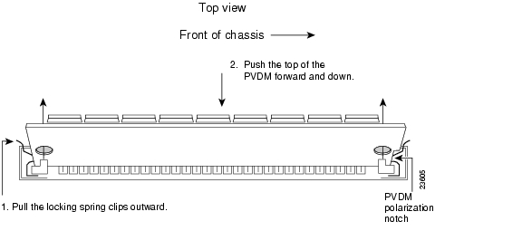
Removing PVDMs
To remove PVDMs, follow these steps:
Step 1
Caution
Step 2
Figure 8-9 Removing PVDMs
Step 3
Step 4
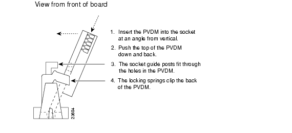
Installing PVDMs
To install PVDMs, follow these steps:
Step 1
Caution
Step 2
Step 3
Step 4
Figure 8-10 Installing PVDMs
Caution
Step 5
Voice Network Module LEDs
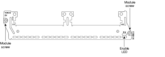
All network modules have an enable (EN) LED. This LED indicates that the module has passed its self-tests and is available to the router. The following network modules have no additional LEDs. (See Figure 8-11 for a sample faceplate.)
•
•
•
•
•
Figure 8-11 Voice Network Module LED
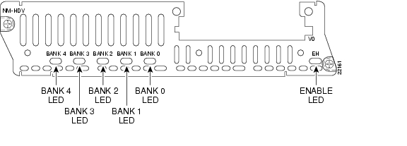
HDV Network Module LEDs
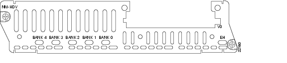
High-density network modules have an enable (EN) LED, and five LEDs for the PVDM banks, numbered 0 through 4. The enable LED indicates that the module has passed its self-tests and is available to the router. The BANK 0 through BANK 4 LEDs indicate the current operating condition of the PVDMs installed on the card. (See Figure 8-12.) If the BANK LEDs do not come on after initial installation and configuration, check that the PVDMs are properly seated in their slots.
Figure 8-12 HDV Network Module LEDs
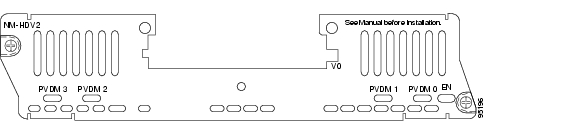
IP Communications High-Density Digital Voice or Fax Network Module
This section describes the IP communications high-density digital voice or fax (NM-HDV2) network module. This module is available in three base-board stock-keeping units (SKUs):
•
•
•
These three base-board SKUs also include a single VIC or VWIC slot for Foreign Exchange Station (FXS), Foreign Exchange Office (FXO) or centralized automated message accounting trunk protocol (CAMA), receive and transmit (E&M), Direct Inward Dial (DID), Basic Rate Interface (BRI), or E1/T1 interface cards.
Figure 8-13 NM-HDV2
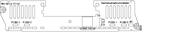
Figure 8-14 NM-HDV2-1T1/E1
Figure 8-15 NM-HDV2-2T1/E1
The NM-HDV2 network module converts voice and fax into IP packets or frames that can be transmitted as VoIP over a variety of transport technologies (channelized T1, Frame Relay, Asynchronous Transfer Mode [ATM], and others).
Packet Fax or Voice DSP Modules
The packet fax or voice digital signal processor (DSP) module (PVDM2) is available in five stock-keeping units (SKUs):
You can install up to four PVDM2 modules on all of the NM-HDV2 SKUs. The number of channels supported depends on the number and density-type of PVDM2 modules installed.
Table 8-2 Channels Per PVDM2 Module Type
PVDM2-8
4
4
4-8
PVDM2-16
6
8
6-16
PVDM2-32
12
16
12-32
PVDM2-48
18
24
18-48
PVDM2-64
24
32
24-64
1 High-complexity vocoders supported: G.711, G.726, G.729, G.723.1, G.728, and Fax Relay.
2 Medium-complexity vocoders supported: G.711, G.726, G.729a, and Fax Relay.
3 Flexi vocoders supported: G.711, G.726, G.729, G.723.1, G.728, and Fax Relay (number of channels depends on codec selected).
Note
When used with PVDM2 modules and either the built-in T1/E1 ports or the T1/E1 voice or WAN interface cards (VWIC), the NM-HDV2 network module provides the interface to the PBX, the PSTN, or WAN. The following VWICs are supported:
•
•
•
•
•
•
•
•
When used with PVDM2 modules and next-generation analog or BRI voice interface cards (VIC2), the NM-HDV2 network module provides the interface to telephony equipment (PBX, key systems, telephones, and fax machines) and to the PSTN. The following VICs are supported:
•
•
•
•
•
•
•
•
Configuring E1 Ports for Normal or Wetting Current Mode
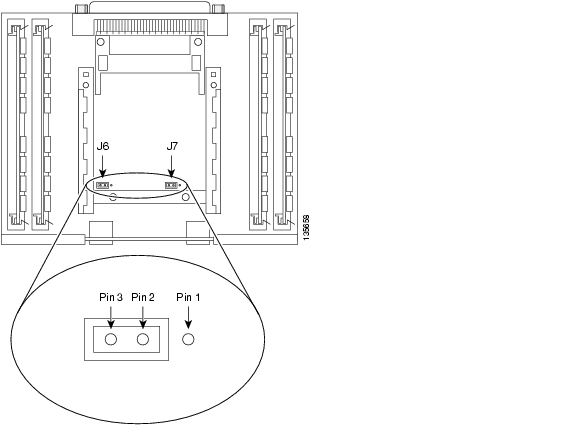
On the NM-HDV2-1T1/E1 and NM-HDV2-2T1/E1 network modules there is a jumper block for each built-in T1/E1 port that controls whether the port supports normal or wetting current mode. Wetting current is a small amount of electrical current (60 to 140 milliamps) sent from the central office to the card to prevent the corrosion of electrical contacts in the module's network connection. Depending on how your E1 line is provisioned, you might have to change the jumper setting on the network module to allow proper operation.
The jumper blocks are identified on the printed circuit board of the NM-HDV2-1T1/E1 and NM-HDV2-2T1/E1 network modules as J6 and J7. (See Figure 8-16.) J6 is the jumper block for T1/E1 controller 1 and J7 is the jumper block for T1/E1 controller 0. The pins on each jumper block are numbered 1 to 3 from right to left.
•
•
Figure 8-16 shows the jumper block configured for normal mode, with the jumper set to pins 2 and 3.
Tip
Figure 8-16 NM-HDV2-2T1/E1 Jumpers Configured for Normal Mode
Installing PVDM2 Modules
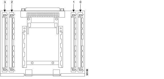
The NM-HDV2 network modules contain four 80-pin SIMM sockets for PVDM2 modules, numbered 0 through 3. (See Figure 8-17.) Each socket can be filled with a single 80-pin PVDM2 module.
Figure 8-17 PVDM2 Module Slot Locations
PVDM2 Module Orientation
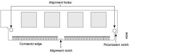
PVDM2 modules are manufactured with a polarization notch to ensure proper orientation, and alignment holes to ensure proper positioning. Figure 8-18 shows the polarization notch and alignment holes on a PVDM2 module. PVDM2 modules are installed with the connector edge down, the polarization notch near the back of the chassis.
Caution
Figure 8-18 PVDM2 Module Orientation
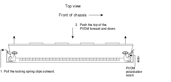
Removing PVDM2 Modules
To remove PVDM2 modules, follow these steps:
Step 1
Caution
Step 2
Figure 8-19 Removing PVDM2 Modules
Step 3
Step 4
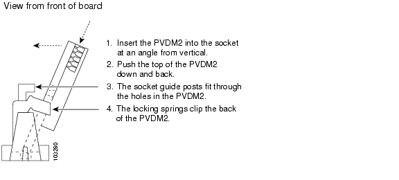
Installing PVDM2 Modules
To install PVDM2 modules, follow these steps:
Step 1
Caution
Step 2
Step 3
Step 4
Note
Figure 8-20 Installing PVDM2 Modules
Caution
Step 5
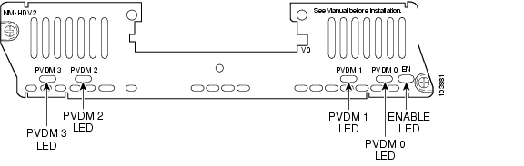
NM-HDV2 Network Module LEDs
IP communications high-density digital voice or fax (NM-HDV2) network modules have an enable (EN) LED, and four LEDs for the PVDM2 modules, numbered 0 through 3. The enable LED indicates that the module has passed its self-tests and is available to the router. The PVDM 0 through PVDM 3 LEDs indicate the current operating condition of the PVDM2 modules installed on the card. (See Figure 8-21.) If the PVDM LEDs are not green after initial installation and configuration, check that the PVDM2 modules are properly seated in their slots.
Figure 8-21 NM-HDV2 Network Module LEDs
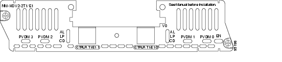
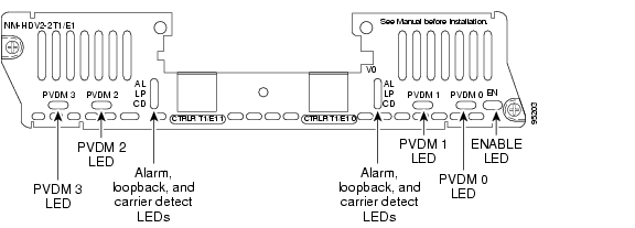
The NM-HDV2-1T1/E1 and NM-HDV2-2T1/E1 network modules have LEDs monitoring the alarm (AL), loopback (LP), and carrier detection (CD) conditions of the built-in T1/E1 ports. (See Figure 8-22.)
Figure 8-22 NM-HDV2-2T1/E1 LEDs
![]()
![]()
![]()
![]()
![]()
![]()
![]()
![]()
Posted: Fri Dec 14 11:45:04 PST 2007
All contents are Copyright © 1992--2007 Cisco Systems, Inc. All rights reserved.
Important Notices and Privacy Statement.