|
|

Table Of Contents
Connecting ISDN PRI Network Modules
Channelized T1/E1 PRI Network Modules with G.703
Enabling Wetting Current on Channelized T1/E1 PRI Network Modules with G.703
Connecting Channelized T1/E1 PRI Network Modules with G.703 to a Network
Channelized T1/ISDN PRI Network Modules
Connecting CT1/PRI Modules to the Network
Channelized T1/ISDN PRI with CSU Network Modules
Connecting CT1/PRI CSU Modules to the Network
Channelized E1/ISDN PRI Balanced (120-Ohm) Network Modules
CE1/PRI Module Jumper Settings
Connecting CE1/PRI-B Modules to the Network
Channelized E1/ISDN PRI Unbalanced (75-Ohm) Network Modules
CE1/PRI Module Jumper Settings
Connecting CE1/PRI-U Modules to the Network
Channelized T1/E1 PRI Network Module with G.703 LEDs
CT1/PRI CSU Network Module LEDs
Online Insertion and Removal with a Cisco PRI Network Module (Cisco 3660 and Cisco 3745 Only)
Upgrading ISDN PRI Network Modules
Connecting ISDN PRI Network Modules
This chapter describes how to connect Integrated Services Digital Network (ISDN) Primary Rate Interface (PRI) network modules for Cisco modular routers and contains the following sections:
•
Channelized T1/E1 PRI Network Modules with G.703
•
•
•
•
•
•
Note
Note
Note
Tip
CT1/PRI modules are available with or without a built-in channel service unit (CSU), and with one or two ports. CT1/PRI modules connect to an external CSU; CT1/PRI-CSU modules connect directly to the network. Each T1 module provides up to 24 virtual channels per T1 port. Each channel can be configured individually as a serial interface.
CT1/PRI and CT1/PRI-CSU modules receive and transmit data bidirectionally, at the T1 rate of 1.544 Mbps.
Channelized T1/E1 PRI Network Modules with G.703
This section provides information about the following network modules:
•
•
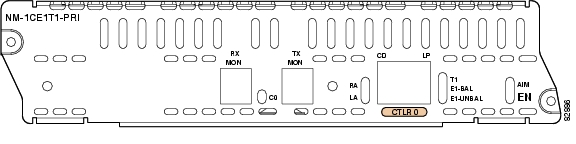
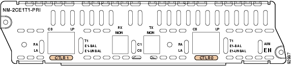
Cisco T1/E1 channelized PRI network modules with G.703 provide connection of one or two primary rate ISDN lines. T1 or E1 interfaces are configurable through Cisco IOS command-line interface (CLI) commands. Each port supports 100/120-ohm balanced and 75-ohm unbalanced termination, and features RJ-48C connectors and cable accessories allowing for DB-15, BNC, and other connector types. An onboard advanced integration module (AIM) connector allows for future universal port AIM support.
Caution
Cisco T1/E1 channelized PRI network modules with G.703 (NM-1CE1T1-PRI and NM-2CE1T1-PRI) replace the following network modules (also described in this chapter):
•
•
•
•
•
•
•
•
For information on Cisco modular access routers supporting Cisco channelized T1/E1 PRI network modules with G.703, see Table 7-1.
Figure 7-1 and Figure 7-2 show the faceplates for the 1-port and 2-port channelized T1/E1 PRI network modules with G.703.
Figure 7-1 1-Port Channelized T1/E1 PRI Network Module with G.703
Figure 7-2 2-Port Channelized T1/E1 PRI Network Module with G.703
Enabling Wetting Current on Channelized T1/E1 PRI Network Modules with G.703
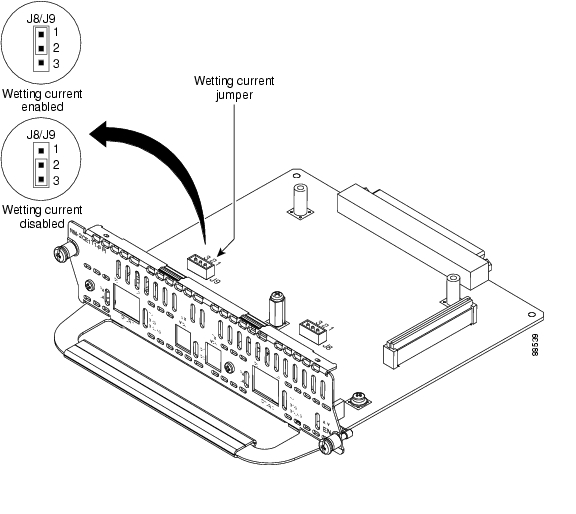
Wetting current is a small amount of electrical current (60 to 140 milliamps) sent from the central office to the card to prevent the corrosion of electrical contacts in the module network connection.
The wetting current feature can be enabled or disabled by the end user. It is controlled by the location of a jumper on the J8 (CTLR 0) and J9 (CTLR 1) connectors on the network module. (See Figure 7-3.)
To enable the wetting current feature, connect pins 1 and 2 on the J8 and J9 connectors with the jumper. To disable the wetting current feature, either remove the jumper completely, or use the jumper to connect pins 2 and 3 on the J8 and J9 connectors.
The card is shipped with the jumper connecting pins 2 and 3 on the J8 and J9 connectors, disabling the wetting current feature.
Figure 7-3 Wetting Current Jumper Locations on Channelized T1/E1 PRI Network Modules with G.703
Connecting Channelized T1/E1 PRI Network Modules with G.703 to a Network
Warning
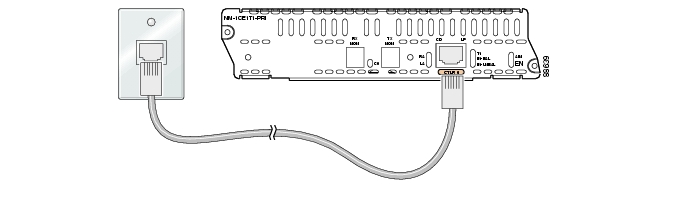
Figure 7-4 shows a connection between a channelized T1/E1 PRI network module with G.703 and a networking device.
Caution
Figure 7-4 Connecting a Channelized T1/E1 PRI Network Module with G.703 to a Networking Device
Channelized T1/ISDN PRI Network Modules
This section provides information about the following network modules for Cisco modular routers:
•
•
Figure 7-5 1-Port Channelized T1/ISDN PRI Network Module
Figure 7-6 2-Port Channelized T1/ISDN PRI Network Module
Connecting CT1/PRI Modules to the Network
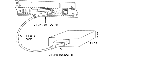
To connect a CT1/PRI module to the network, use a DB-15-to-DB-15 T1 serial cable to connect the CT1/PRI port to a T1 channel service unit (CSU). (See Figure 7-7.) These ports are color-coded tan.
Figure 7-7 Connecting a CT1/PRI Module to a T1 CSU
Channelized T1/ISDN PRI with CSU Network Modules
This section provides information about the following network modules for Cisco modular routers:
•
•
Figure 7-8 1-Port Channelized T1/ISDN PRI with CSU Network Module
Figure 7-9 2-Port Channelized T1/ISDN PRI with CSU Network Module
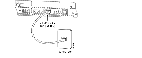
Connecting CT1/PRI CSU Modules to the Network
To connect a CT1/PRI CSU module to the network, use a straight-through RJ-48C-to-RJ-48C cable to connect the RJ-48C port to an RJ-48C jack (see Figure 7-10). These ports are color-coded tan.
Figure 7-10 Connecting a CT1/PRI CSU Module to an RJ-48C Jack
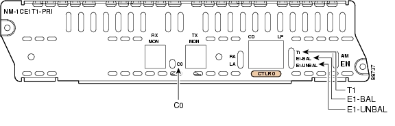
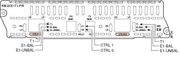
Channelized E1/ISDN PRI Balanced (120-Ohm) Network Modules
This section provides information about the following network modules for Cisco modular routers:
•
•
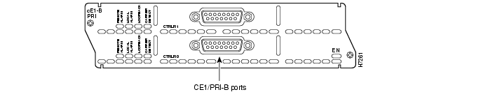
Figure 7-11 1-Port Channelized E1/ISDN PRI Network Module (Balanced)
Figure 7-12 2-Port Channelized E1/ISDN PRI Network Module (Balanced)
CE1/PRI modules are available with one or two E1 ports and with balanced or unbalanced interfaces. These modules receive and transmit data bidirectionally at the E1 rate of 2.048 Mbps, and provide up to 30 virtual channels per E1 port. Each channel can be configured individually as a serial interface.
CE1/PRI Module Jumper Settings
Jumpers on CE1/PRI modules can be used to connect or disconnect receive shield to ground. (See Table 7-2.) The default setting for balanced, 120-ohm CE1/PRI-B modules disconnects receive shield to ground. The default setting for unbalanced, 75-ohm CE1/PRI-U modules connects receive shield to ground. If you are experiencing ground loop problems with E1 cabling, you may want to try changing the jumper settings for the module.
Connecting CE1/PRI-B Modules to the Network
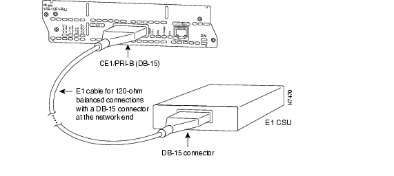
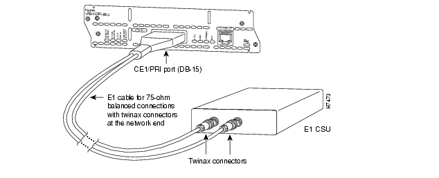
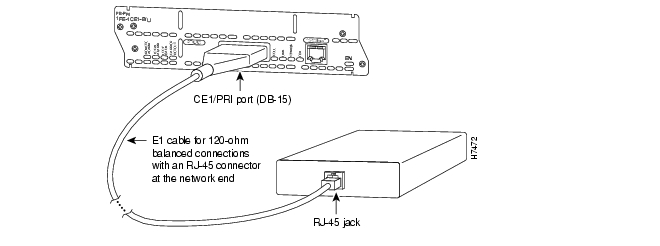
To connect a CE1/PRI-B (120-ohm) module to the network, use the appropriate cable to connect the CE1/PRI-B port to an E1 CSU. (See Figure 7-13, Figure 7-14, and Figure 7-15, showing DB-15, twinax, and RJ-45 CSUs, respectively.) These ports are color-coded tan.
Figure 7-13 Connecting a 120-ohm CE1/PRI-B Module to an E1 CSU (DB-15-to-DB-15 Connectors)
Figure 7-14 Connecting a 120-ohm CE1/PRI-B Module to an E1 CSU (DB-15-to-Twinax Connectors)
Figure 7-15 Connecting a 120-ohm CE1/PRI-B Module to an E1 CSU (DB-15-to-RJ-45 Connectors)
Channelized E1/ISDN PRI Unbalanced (75-Ohm) Network Modules
This section provides information about the following network modules for Cisco modular routers:
•
•
Figure 7-16 1-Port Channelized E1/ISDN PRI Network Module (Unbalanced)
Figure 7-17 2-Port Channelized E1/ISDN PRI Network Module (Unbalanced)
CE1/PRI Module Jumper Settings
Jumpers on CE1/PRI modules can be used to connect or disconnect receive shield to ground (see Table 7-3). The default setting for balanced, 120-ohm CE1/PRI-B modules disconnects receive shield to ground. The default setting for unbalanced, 75-ohm CE1/PRI-U modules connects receive shield to ground. If you are experiencing ground loop problems with E1 cabling, you may want to try changing the jumper settings for the module.
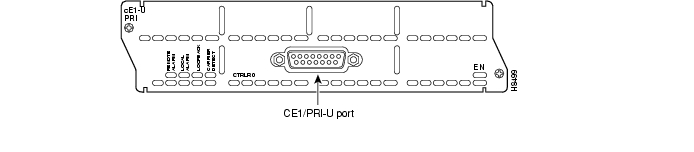
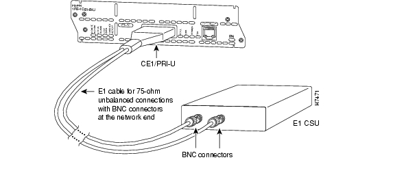
Connecting CE1/PRI-U Modules to the Network
To connect a CE1/PRI-U (75-ohm) module to the network, use the appropriate cable to connect the CE1/PRI-U port to an E1 CSU (see Figure 7-18). These ports are color-coded tan. The illustration shows a CSU with BNC connectors.
Figure 7-18 Connecting a CE1/PRI-U Module to an E1 CSU
(DB-15-to-BNC Connectors)
PRI Module LEDs
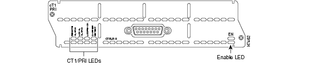
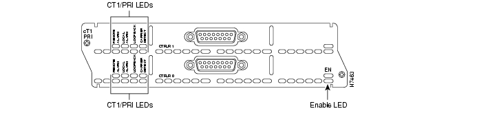
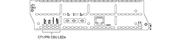
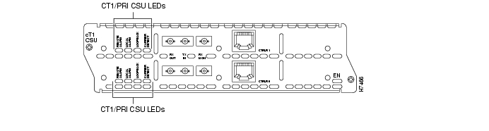
All network modules have an enable (EN) LED. This LED indicates that the module has passed its self-tests and is available to the router.
All PRI modules display four additional LEDs for each port. These LEDs are described in Table 7-4.
Channelized T1/E1 PRI Network Module with G.703 LEDs
Figure 7-19 and Figure 7-20 show channelized T1/E1 PRI network module with G.703 LEDs. See Table 7-5 for LED definitions.
For LEDs found on all PRI network modules, see Table 7-4.
Figure 7-19 1-Port Channelized T1/E1 PRI Network Module with G.703 LEDs
Figure 7-20 2-Port Channelized T1/E1 PRI Network Module with G.703 LEDs
CT1/PRI Network Module LEDs
Figure 7-21 and Figure 7-22 show CT1/PRI network module LEDs.
Figure 7-21 1-Port CT1/PRI Network Module LEDs
Figure 7-22 2-Port CT1/PRI Network Module LEDs
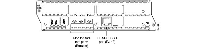
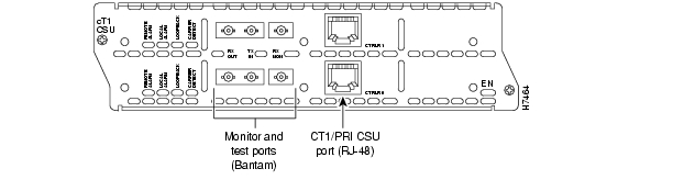
CT1/PRI CSU Network Module LEDs
Figure 7-23 and Figure 7-24 show CT1/PRI CSU module LEDs.
Figure 7-23 1-Port CT1/PRI CSU Network Module LEDs
Figure 7-24 2-Port CT1/PRI CSU Network Module LEDs
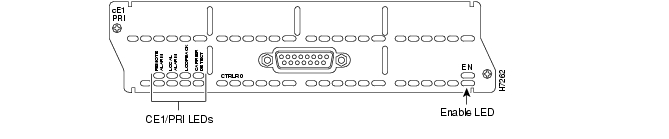
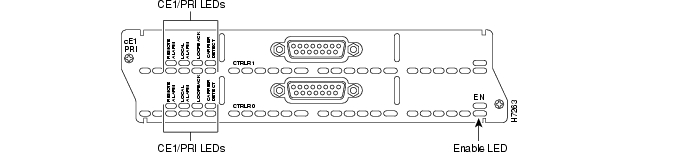
CE1/PRI Network Module LEDs
Figure 7-25 and Figure 7-26 show CE1/PRI module LEDs. These LEDs are the same for balanced and unbalanced modules.
Figure 7-25 1-Port CE1/PRI Network Module LEDs
Figure 7-26 2-Port CE1/PRI Network Module LEDs
Online Insertion and Removal with a Cisco PRI Network Module (Cisco 3660 and Cisco 3745 Only)
Some Cisco modular access routers allow you to replace network modules without switching off the router or affecting the operation of other interfaces. This feature is called online insertion and removal (OIR). OIR of network modules provides uninterrupted operation to network users, maintains routing information, and ensures session preservation.
Note
Caution
For a description of informational and error messages that may appear on the console during this procedure, refer to the hardware installation guide for your type of router.
Upgrading ISDN PRI Network Modules
If your Cisco 3600 series router contains a legacy ISDN PRI network module and a digital modem network module (product numbers NM-6DM, NM-12DM, NM-18DM, NM-24DM, or NM-30DM), your ISDN PRI network module may need to be upgraded to revision level -03 or higher. Earlier revisions of ISDN PRI network modules cannot send modem calls to the digital modem network module.
Note
If your PRI module is the wrong revision, you see a message similar to the following message when the router boots:
The PRI network module in slot 0 is incompatible with the digital modems installed in the
router.
To determine the revision level, you can examine the network module itself (outside the router) or use the Cisco IOS show diag command. The label on the module board should show a part number beginning with 800- and ending with the revision level.
The output of the show diag command looks similar to the following:
Port adapter is analyzedPort adapter insertion time unknownHardware revision 1.0 Board revision A0Serial number 4152626 Part number 800-01236-01Test history 0x0 RMA number 00-00-00EEPROM format version 1EEPROM contents (hex):0x20: 01 26 01 00 00 3F 5D 32 50 04 CC 01 00 00 00 000x30: 50 00 00 00 96 11 04 17 FF FF FF FF FF FF FF FF
![]()
![]()
![]()
![]()
![]()
![]()
![]()
![]()
Posted: Fri Dec 14 11:43:37 PST 2007
All contents are Copyright © 1992--2007 Cisco Systems, Inc. All rights reserved.
Important Notices and Privacy Statement.