|
|

Table Of Contents
Connecting Digital Modem Network Modules
Digital Network Modem Network Modules Overview
Hardware and Software Requirements
Adding 6-Port MICA Modules to a Digital Modem Network Module
Removing the Digital Modem Network Module
Installing 6-Port MICA Modules
Reinstalling the Digital Modem Network Module
Connecting Digital Modem Network Modules
This chapter describes how to connect 6-, 12-, 18-, 24-, and 30-port digital modem network modules (NM-6DM, NM-12DM, NM-18DM, NM-24DM, and NM-30DM) for Cisco modular routers and contains the following sections:
•
Digital Network Modem Network Modules Overview
•
Tip
Digital Network Modem Network Modules Overview
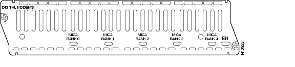
These modules (see Figure 9-1) contain 6, 12, 18, 24, or 30 V.34+ digital modems for a direct digital connection to an Integrated Services Digital Network (ISDN) Primary Rate Interface (PRI) or Basic Rate Interface (BRI) channel, allowing you to mix digital and analog calls to provide remote access to a LAN.
Figure 9-1 Digital Modem Network Module
Digital modem network modules do not provide network interfaces of their own, but instead handle analog calls passing through other router interfaces. In addition to the digital modem module, the router must contain a PRI or BRI interface to connect to the ISDN channel, and another interface, such as Ethernet, to provide connectivity to the LAN. The PRI or BRI module concurrently handles digital ISDN data connections and remote voice-channel (analog) modem connections, allowing a dynamic mix of digital and modem connections. The digital modem module acts as a pool of available modems that can be used for both incoming and outgoing calls.
The digital modems support all standard data rates from 300 bps through 33.6 kbps (V.34 bis); V.42 bis and MNP 5 data compression; and V.42, LAPM, and MNP 4 error correction.
Each digital modem module contains from one to five banks of 6-port modem ISDN channel aggregation (MICA) modules. You can add modems to a module, in groups of six, by installing additional MICA modules (Cisco product number MICA-6MOD), up to a maximum of 30 modems.
Hardware and Software Requirements
In addition to the digital modem module, the router must contain a PRI or BRI network interface to connect to the ISDN channel, and another interface, such as Ethernet or Fast Ethernet, to provide connectivity to the LAN.
A PRI network module (NM-1CT1, NM-2CT1, NM-1CT1-CSU, NM-2CT1-CSU, NM-1CE1B, NM-2CE1B, NM-1CE1U, or NM-2CE1U) used with a digital modem module must be revision level -03 or higher. A BRI S/T network module (NM-4B-S/T or NM-8B-S/T) must be revision level -03 or higher, and a BRI U module (NM-4B-U or NM-8B-U) must be revision level -06 or higher. Earlier revisions of these network modules cannot send modem calls to the digital modem module.
If the PRI or BRI module is the wrong revision, you see a message similar to this one when the router boots:
The T1 or E1 network module in slot 0 is incompatible with the digital modems installed in
the router.
To determine the revision level, you can examine the network module itself (outside the router), or use the Cisco IOS show diag command. The label on the module board should show a part number beginning with 800- and ending with the revision level. The output of the show diag command looks similar to the following:
Slot 3:Port adapter is analyzedPort adapter insertion time unknownHardware revision 1.0 Board revision A0Serial number 4152626 Part number 800-01228-01Test history 0x0 RMA number 00-00-00EEPROM format version 1EEPROM contents (hex):0x20: 01 26 01 00 00 3F 5D 32 50 04 CC 01 00 00 00 000x30: 50 00 00 00 96 11 04 17 FF FF FF FF FF FF FF FFTo order network module upgrades, see the "Obtaining Technical Assistance" section on page xi.
Interface Numbering
Individual digital modem ports are not physically distinct, but Cisco IOS software identifies each modem uniquely through its slot number and port number. Slot numbering is explained in the "Network Module Slot Locations and Numbering on Cisco Access Routers" section on page 1-3.
Each digital modem module can hold up to five banks of MICA modules, numbered 0 to 4 from left to right (as viewed from the rear of the router). Each MICA module holds six modems, which are assigned modem numbers 0 to 5.
Each modem in a digital modem module is also assigned a port number in the range 0 to 29. Modems in the left MICA module (as viewed from the rear of the router), bank 0, are assigned port numbers 0 to 5. Additional MICA modules, if present, are assigned port numbers as follows:
port-number = (6 x bank-number) + modem-number
For example, the third modem (modem 2) in the second MICA module from the left (bank 1) is assigned port number (6 x 1) + 2 = 8.
Some Cisco IOS commands identify ports by interface number (or line number or TTY number, which is the same as the interface number) rather than slot and port number. The interface number of a modem port is related to its slot and port number in the following way:
interface-number = (32 x slot-number) + port-number + 1
This can also be expressed as:
interface-number = (32 x slot-number) + ((6 x bank-number) + modem-number) + 1
For example, if the module containing the modem in the last example is placed in slot 2, the modem is assigned interface number (32 x 2) + ((6 x 1) + 2) + 1 = (32 x 2) + 8 + 1 = 73. This is also the line and TTY number for the port. The modem in this position is always assigned interface 73, whether or not there are other MICA modules in the digital modem network module or other digital modem network modules in the router chassis. If you move the MICA module to a different position in the digital modem network module, however, or move the digital modem network module to a different slot in the router chassis, the interface number changes.
Table 9-1 shows the range of interface numbers available in each router slot. Interface 0 is automatically assigned to the console.
Table 9-1 Digital Modem Network Module Interface Numbering
0
1-30
1
33-62
2
65-94
3
97-126
4
129-158
5
161-190
6
193-222
Adding 6-Port MICA Modules to a Digital Modem Network Module
You can add modems to a digital modem network module, in groups of six, by installing additional 6-port MICA modules, up to a maximum of five MICA modules (30 modems).
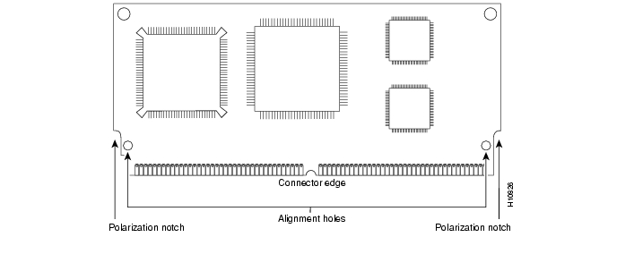
MICA modules are manufactured with a polarization notch to ensure proper orientation, and alignment holes that fit over guide posts to ensure proper positioning. (See Figure 9-2.)
Figure 9-2 6-Port MICA Module
Caution
To remove, replace, or install a MICA module, you must first remove the digital modem module from the router chassis.
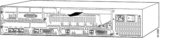
Removing the Digital Modem Network Module
Caution
To remove a digital modem network module, follow these steps:
Step 1
The following warning applies to routers that use a DC power supply:
Warning
Step 2
Step 3
Step 4
Figure 9-3 Removing a Digital Modem Network Module from a Router
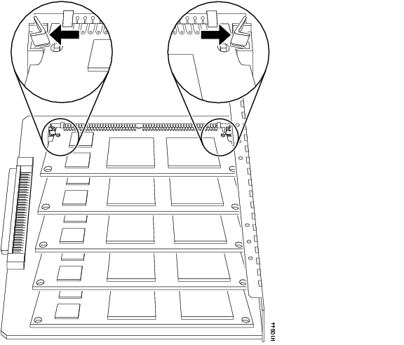
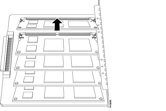
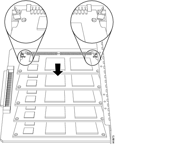
Removing 6-Port MICA Modules
To remove a MICA module from the digital modem network module, follow these steps:
Step 1
Caution
Step 2
Step 3
Step 4
Step 5
Figure 9-4 Releasing the Mounting Clips
Figure 9-5 Tilting a 6-Port MICA Module Free of the Mounting Clips
Figure 9-6 Lifting a 6-Port MICA Module Out of the Socket
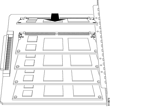
Installing 6-Port MICA Modules
To install new or replacement MICA modules, follow these steps:
Step 1
Caution
Step 2
Step 3
Step 4
Step 5
Figure 9-7 Inserting a 6-Port MICA Module into a Socket
Figure 9-8 Rocking a 6-Port MICA Module Downward
Reinstalling the Digital Modem Network Module
When you finish installing MICA modules, replace the digital modem network module in the router chassis, following these steps:
Step 1
Step 2
Step 3
Step 4
The following warning applies to routers that use a DC power supply:
Warning
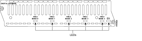
Digital Modem Module LEDs
All network modules have an enable (EN) LED. (See Figure 9-9.) This LED indicates that the module has passed its self-tests and is available to the router.
Digital modem modules have five additional LEDs, one for each MICA module bank. The LEDs blink during initialization. After the enable LED comes on, the MICA module LEDs indicate that the corresponding MICA module is functioning. If a MICA module fails its diagnostics, or if no MICA module is installed in a position, its LED remains off.
Figure 9-9 Digital Modem Network Module LEDs
![]()
![]()
![]()
![]()
![]()
![]()
![]()
![]()
Posted: Fri Dec 14 11:42:35 PST 2007
All contents are Copyright © 1992--2007 Cisco Systems, Inc. All rights reserved.
Important Notices and Privacy Statement.