|
|

Table Of Contents
Connecting ISDN BRI Network Modules
4- and 8-Port ISDN BRI S/T Network Modules
Connecting BRI S/T Modules to a Network
4- and 8-Port ISDN BRI U Network Modules
Connecting BRI U Modules to a Network
Upgrading ISDN BRI Network Modules
Connecting ISDN BRI Network Modules
This chapter describes how to connect Integrated Services Digital Network (ISDN) Basic Rate Interface (BRI) network modules for Cisco modular routers and contains the following sections:
•
4- and 8-Port ISDN BRI S/T Network Modules
•
•
Unless specifically identified, references to BRI modules in this chapter include all ISDN BRI network modules.
Note
Tip
4- and 8-Port ISDN BRI S/T Network Modules
This section provides information about the following network modules for Cisco modular routers:
•
•
Figure 6-1 4-Port ISDN BRI Network Module (S/T Interface)
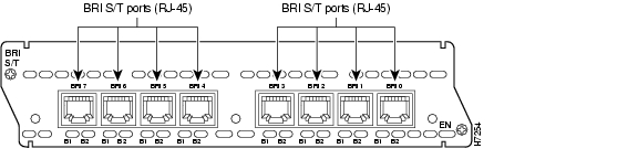
Figure 6-2 8-Port ISDN BRI Network Module (S/T Interface)
Connecting BRI S/T Modules to a Network
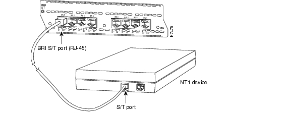
To connect a BRI S/T network module to a network, use a straight-through RJ-45-to-RJ-45 cable to connect the ISDN BRI port to an NT1. (See Figure 6-3.) These ports are color-coded orange.
Figure 6-3 Connecting an ISDN BRI S/T Network Module to an NT1
BRI S/T Module LEDs
Figure 6-4 shows LEDs for the 4-port BRI S/T network module. Figure 6-5 shows LEDs for the 8-port BRI S/T network module.
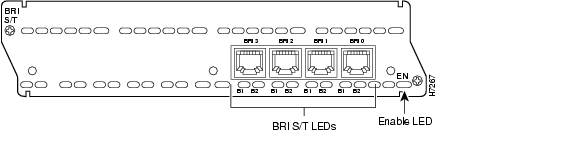
Figure 6-4 4-Port ISDN BRI S/T Network Module LEDs
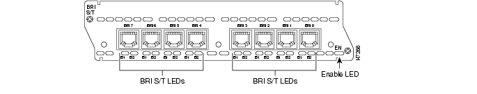
Figure 6-5 8-Port ISDN BRI S/T Network Module LEDs
All network modules have an enable (EN) LED. This LED indicates that the module has passed its self-tests and is available to the router.
In addition, BRI S/T modules have two LEDs for each port. These LEDs indicate call activity on the two ISDN BRI B channels, as described in Table 6-1.
Table 6-1 BRI S/T Network Module LEDs
B1
Call active on B1 channel
B2
Call active on B2 channel
4- and 8-Port ISDN BRI U Network Modules
This section provides information about the following network modules for Cisco modular routers:
•
•
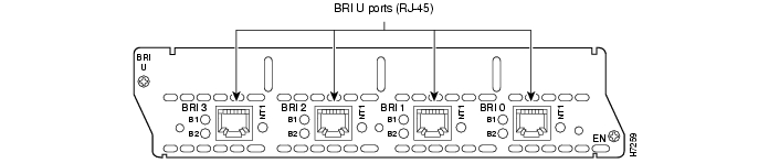
Figure 6-6 4-Port ISDN BRI with NT1 Network Module (U Interface)
Figure 6-7 8-Port ISDN BRI with NT1 Network Module (U Interface)
Connecting BRI U Modules to a Network
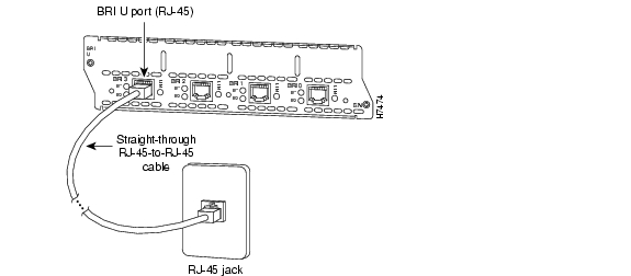
To connect a BRI U module to a network, use a straight-through RJ-45-to-RJ-45 cable to connect the ISDN BRI port to an RJ-45 jack. (See Figure 6-8.) These ports are color-coded red.
Figure 6-8 Connecting a BRI U Network Module to an RJ-45 ISDN Jack
BRI U Module LEDs
Figure 6-9 shows LEDs for the 4-port BRI U network module. Figure 6-10 shows LEDs for the 8-port BRI U network module.
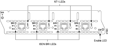
Figure 6-9 4-Port ISDN BRI U Network Module LEDs
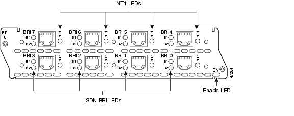
Figure 6-10 8-Port ISDN BRI U Network Module LEDs
All network modules have an enable (EN) LED. This LED indicates that the module has passed its self-tests and is available to the router.
In addition, BRI U modules have three LEDs for each port. Two of these LEDs indicate call activity on the two ISDN BRI B channels, as described in Table 6-2. The third LED, labeled NT1, indicates synchronization status of the NT1.
Table 6-2 BRI U Network Modules LEDs
B1
Activity on B1 channel
B2
Activity on B2 channel
NT1
Synchronous status of NT1
Upgrading ISDN BRI Network Modules
If your Cisco 3600 series router contains an ISDN BRI network module (product numbers NM-4B-S/T, NM-4B-U, NM-8B-S/T, or NM-8B-U) and a digital modem network module (product numbers NM-6DM, NM-12DM, NM-18DM, NM-24DM, or NM-30DM), your ISDN BRI network module may need to be upgraded to the minimum revision shown in Table 6-3.
Earlier revisions of the ISDN BRI network module cannot send modem calls to the digital modem network module.
Table 6-3 ISDN BRI Network Module Upgrade Revisions
NM-4B-S/T
800-01236-03
NM-4B-U
800-01238-06
NM-8B-S/T
800-01237-03
NM-8B-U
800-01239-06
If your BRI module is the wrong revision, you see a message similar to this one when the router boots:
The BRI network module in slot 0 is incompatible with the digital modems installed in the
router.
To determine the revision level, you can examine the network module itself (outside the router) or use the Cisco IOS show diag command. The label on the module board should show a part number beginning with 800-, corresponding to Table 6-3. A BRI S/T module whose part number ends with -01 or -02 needs to be upgraded, as does a BRI U module whose part number is lower than -06.
The output of the show diag command looks similar to the following:
Port adapter is analyzedPort adapter insertion time unknownHardware revision 1.0 Board revision A0Serial number 4152626 Part number 800-01236-01Test history 0x0 RMA number 00-00-00EEPROM format version 1EEPROM contents (hex):0x20: 01 26 01 00 00 3F 5D 32 50 04 CC 01 00 00 00 000x30: 50 00 00 00 96 11 04 17 FF FF FF FF FF FF FF FFTo order network module upgrades, see the "Obtaining Technical Assistance" section on page xi.
![]()
![]()
![]()
![]()
![]()
![]()
![]()
![]()
Posted: Fri Dec 14 11:43:49 PST 2007
All contents are Copyright © 1992--2007 Cisco Systems, Inc. All rights reserved.
Important Notices and Privacy Statement.