|
|

Table Of Contents
Connecting Fast Ethernet-PRI Network Modules
1-Port Fast Ethernet and 1- or 2-Port Channelized T1/ISDN PRI Network Modules
Connecting Fast Ethernet Channelized T1 Modules
1-Port Fast Ethernet and 1- or 2-Port Channelized T1/ISDN PRI with CSU Network Modules
Connecting Fast Ethernet Channelized T1 with CSU Modules
1-Port Fast Ethernet and 1- or 2-Port Channelized E1/ISDN PRI Balanced or Unbalanced Network Modules
Connecting Fast Ethernet Channelized E1 Modules
Setting Interfaces to Balanced or Unbalanced Termination
Connecting Fast Ethernet-PRI Network Modules
This chapter describes how to connect Fast Ethernet-Integrated Services Digital Network (ISDN) Primary Rate Interface (PRI) network modules and contains the following sections:
•
1-Port Fast Ethernet and 1- or 2-Port Channelized T1/ISDN PRI Network Modules
•
•
•
Note
Tip
1-Port Fast Ethernet and 1- or 2-Port Channelized T1/ISDN PRI Network Modules
This section provides information about the following network modules:
•
•
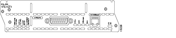
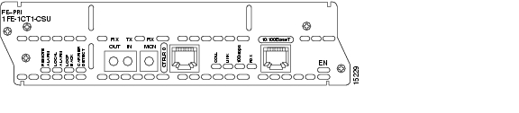
Figure 4-1 1-Port Fast Ethernet 1-Port Channelized T1 Network Module
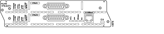
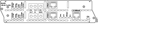
Figure 4-2 1-Port Fast Ethernet 2-Port Channelized T1 Network Module
Connecting Fast Ethernet Channelized T1 Modules
Use the following sections for Fast Ethernet and PRI connections.
Fast Ethernet Port
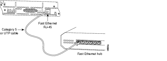
Use a straight-through two-pair Category 5 unshielded twisted-pair (UTP) cable to connect the RJ-45 port on the Fast Ethernet-PRI network module to a switch, hub, repeater, server, or other network device. These ports are color-coded yellow. Figure 4-3 shows the RJ-45 port connected to a hub.
Note
Figure 4-3 Connecting a Fast Ethernet RJ-45 Port to a Hub
PRI Ports
This section describes how to connect channelized T1 and channelized E1 ISDN PRI ports to the network. These ports are color-coded tan.
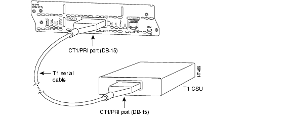
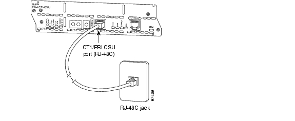
Use a DB-15-to-DB-15 T1 serial cable to connect a CT1/PRI port to a T1 channel service unit (CSU). (See Figure 4-4.)
Figure 4-4 Connecting a CT1/PRI Port to a T1 CSU
1-Port Fast Ethernet and 1- or 2-Port Channelized T1/ISDN PRI with CSU Network Modules
This section provides information about the following network modules:
•
•
Figure 4-5 1-Port Fast Ethernet 1-Port Channelized T1 with CSU Network Module
Figure 4-6 1-Port Fast Ethernet 2-Port Channelized T1 with CSU Network Module
Connecting Fast Ethernet Channelized T1 with CSU Modules
Use the following sections for connections to the Fast Ethernet or CT1/PRI-CSU ports.
Fast Ethernet Port
To connect the Fast Ethernet port, see the "Fast Ethernet Port" section.
CT1/PRI-CSU Port
To connect the CT1/PRI-CSU PRI ports, use a straight-through RJ-48C-to-RJ-48C cable to connect a PRI port to an RJ-48C jack. (See Figure 4-7.) These ports are color-coded tan.
Figure 4-7 Connecting a CT1/PRI-CSU Port to an RJ-48C Jack
1-Port Fast Ethernet and 1- or 2-Port Channelized E1/ISDN PRI Balanced or Unbalanced Network Modules
This section provides information about the following network modules:
•
•
•
•
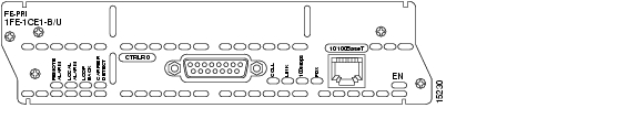
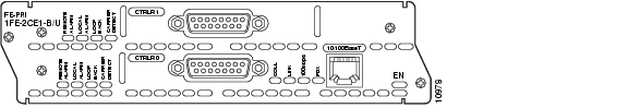
Figure 4-8 1-Port Fast Ethernet 1-Port Channelized E1 Network Module
Figure 4-9 1-Port Fast Ethernet 2-Port Channelized E1 Network Module
Connecting Fast Ethernet Channelized E1 Modules
Use the following sections to connect to the Fast Ethernet or CE1-PRI-B ports.
Fast Ethernet Port
To connect the Fast Ethernet port, see the "Fast Ethernet Port" section.
CE1/PRI-B Port
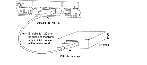
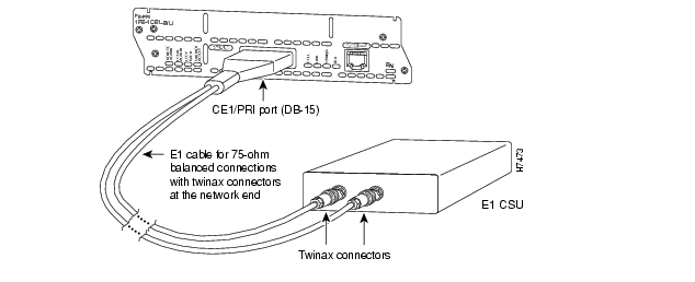
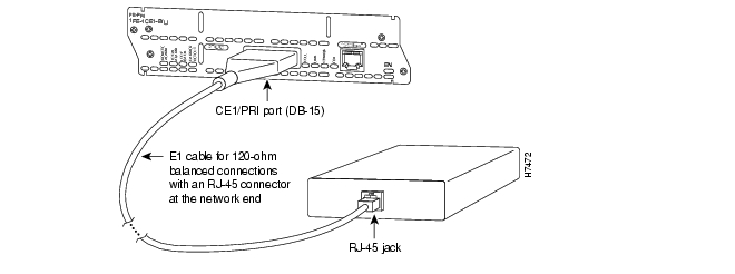
Use the appropriate cable to connect a CE1/PRI-B (120-ohm) port to an E1 CSU. (See Figure 4-10, Figure 4-11, and Figure 4-12, showing DB-15, twinax, and RJ-45 CSUs respectively.) These ports are color-coded tan.
Figure 4-10 Connecting a CE1/PRI-B Port to an E1 CSU (DB-15-to-DB-15 Connectors)
Figure 4-11 Connecting a CE1/PRI-B Port to an E1 CSU (DB-15-to-Twinax Connectors)
Figure 4-12 Connecting a CE1/PRI-B Port to an E1 CSU (DB-15-to-RJ-45 Connectors)
CE1/PRI-U Port
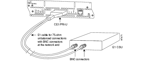
Use the appropriate cable to connect a CE1/PRI-U (75-ohm) port to an E1 CSU. Figure 4-13 shows a CSU with BNC connectors. These ports are color-coded tan.
Figure 4-13 Connecting a CE1/PRI-U Module to an E1 CSU (DB-15-to-BNC Connectors)
Setting Interfaces to Balanced or Unbalanced Termination
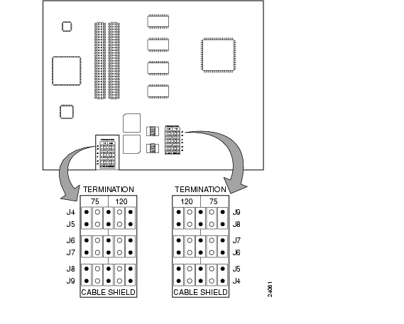
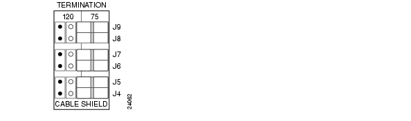
This section describes how to configure an E1 network module for balanced or unbalanced termination. The module consists of two circuit boards, or cards. A terminal block and a set of five jumpers are provided on each card to configure termination. Figure 4-14 shows these terminal blocks.
Caution
Figure 4-14 Terminal Block Locations
Note
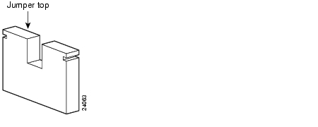
Figure 4-15 shows a typical jumper.
Figure 4-15 Jumper
Configuring Unbalanced Mode
To configure the network module for unbalanced mode, follow these steps:
Step 1
The following warning applies to routers that use a DC power supply:
Warning
Step 2
Step 3
Step 4
Step 5
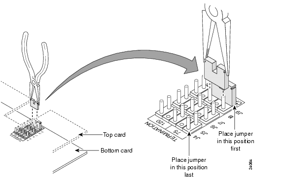
Figure 4-16 Jumper Insertion
Figure 4-17 shows the top terminal block set to unbalanced (75-ohm) position.
Figure 4-17 Jumpers in Unbalanced 75-Ohm Position (Top Card)
Step 6
Step 7
Step 8
Step 9
The following warning applies to routers that use a DC power supply:
Warning
Configuring Balanced Mode
To configure the network module for balanced mode, follow these steps:
Step 1
The following warning applies to routers that use a DC power supply:
Warning
Step 2
Step 3
Step 4
Step 5
Step 6
Step 7
Step 8
Step 9
The following warning applies to routers that use a DC power supply:
Warning
Fast Ethernet-PRI Module LEDs
All network modules have an enable (EN) LED. This LED indicates that the module has passed its self-tests and is available to the router.
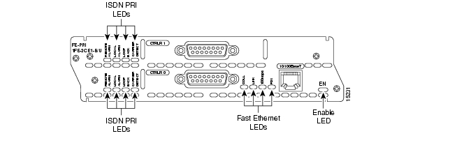
All Fast Ethernet-PRI modules have four LEDS for the Fast Ethernet port, and four additional LEDs for each PRI port. Figure 4-18 shows LEDs for the 1-port Fast Ethernet 2-port channelized E1/ISDN PRI balanced (120-ohm) network module as an example.
Figure 4-18 Fast Ethernet and ISDN PRI LEDs
Table 4-1 describes Fast Ethernet LEDs. Table 4-2 describes ISDN PRI LEDs.
![]()
![]()
![]()
![]()
![]()
![]()
![]()
![]()
Posted: Fri Dec 14 11:39:32 PST 2007
All contents are Copyright © 1992--2007 Cisco Systems, Inc. All rights reserved.
Important Notices and Privacy Statement.