|
|

Table Of Contents
Connecting Gigabit Ethernet Network Modules
Gigabit Ethernet Network Modules
Connecting Gigabit Ethernet Network Modules to the Network
Gigabit Ethernet Network Module LEDs
CWDM Passive Optical System Documentation
Connecting Gigabit Ethernet Network Modules
This chapter describes how to connect Gigabit Ethernet network modules for modular access routers and contains the following sections:
•
Gigabit Ethernet Network Modules
•
Tip
Gigabit Ethernet Network Modules
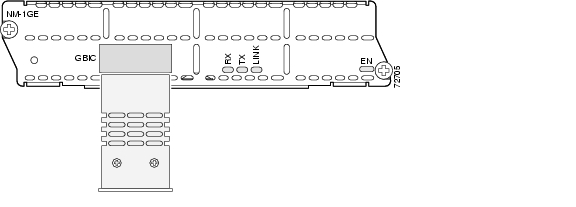
The Gigabit Ethernet network module provides single-port Gigabit Ethernet connectivity through an installed Gigabit interface converter (GBIC). The GBIC determines the type of connectivity available to the network module. (See Figure 21-1.)
Figure 21-1 Gigabit Ethernet Network Module Faceplate
See Table 21-1 for information on connection types supported by each GBIC.
Note
Table 21-1 Gigabit Ethernet Connection and Cable Types Supported on Gigabit Ethernet Network Modules
GBIC-ZX=
Extended distance 1000BASE-ZX
10-micron SMF cable (yellow) with SC connectors1
GBIC-LX/LH=
Long-wavelength or long-haul 1000BASE-LX/LH
10-micron SMF cable (yellow) with SC connectors 1
TipGBIC-SX=
Short-wavelength 1000BASE-SX
62.5-micron MMF cable (orange) with SC connectors
GBIC-T=
UTP Category 5 or 6 1000BASE-T
Category 5 or 6 UTP cable with RJ-45 connectors
CWDM-GBIC-1470=
1000BASE-CWDM GBIC 1470 nm
10-micron SMF cable (yellow) with SC connectors 1
CWDM-GBIC-1490=
1000BASE-CWDM GBIC 1490 nm
10-micron SMF cable (yellow) with SC connectors 1
CWDM-GBIC-1510=
1000BASE-CWDM GBIC 1510 nm
10-micron SMF cable (yellow) with SC connectors 1
CWDM-GBIC-1530=
1000BASE-CWDM GBIC 1530 nm
10-micron SMF cable (yellow) with SC connectors 1
CWDM-GBIC-1550=
1000BASE-CWDM GBIC 1550 nm
10-micron SMF cable (yellow) with SC connectors 1
CWDM-GBIC-1570=
1000BASE-CWDM GBIC 1570 nm
10-micron SMF cable (yellow) with SC connectors 1
CWDM-GBIC-1590=
1000BASE-CWDM GBIC 1590 nm
10-micron SMF cable (yellow) with SC connector 1s
CWDM-GBIC-1610=
1000BASE-CWDM GBIC 1610 nm
10-micron SMF cable (yellow) with SC connectors 1
1 10-dB SMF optical attenuators with SC connectors (two per duplex cable) are required for distances less than 25 km (15.5 miles). Install the attenuators between the male SC connector on the cable and the female SC connector on the network module.
Installing and Removing GBICs
Gigabit Ethernet network modules support GBIC hot-swapping. To save time, do not power down the router and network module before installing or removing the GBIC.
Warning
Note
Step 1
Figure 21-2 Installing a GBIC into a Network Module
Step 2
Step 3
Laser Safety Guidelines
Optical GBICs use a small laser to generate the fiber-optic signal. Keep the transmit port covered whenever a cable is not connected to the port.
The module faceplate carries a Class 1 laser warning label. (See Figure 21-3.)
Figure 21-3 Class 1 Laser Warning Label
Warning
Warning
Connecting Gigabit Ethernet Network Modules to the Network
Warning
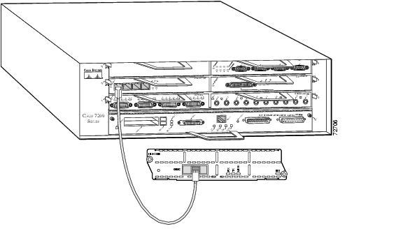
Use the cables listed in Table 21-1 to connect the GBIC connectors on the network module to a networking device. (See Figure 21-4.)
Figure 21-4 Connecting a Gigabit Ethernet Network Module to a Cisco 7200 Series Router
Gigabit Ethernet Network Module LEDs
All network modules have an enable (EN) LED. This LED indicates that the module has passed its self-tests and is available to the router. See Figure 21-5 and Table 21-2 for LEDs specific to the Gigabit Ethernet network module.
Figure 21-5 Gigabit Ethernet Network Module LEDs
Related Documents
For additional information, see the following documents.
Tip
CWDM Passive Optical System Documentation
For more information on the CWDM Passive Optical System, which is often used with CWDM GBICs, see the Cisco 1000BASE-CWDM Series Passive Optical System Installation Note document.
![]()
![]()
![]()
![]()
![]()
![]()
![]()
![]()
Posted: Fri Dec 14 11:58:04 PST 2007
All contents are Copyright © 1992--2007 Cisco Systems, Inc. All rights reserved.
Important Notices and Privacy Statement.