|
|

Table Of Contents
Connecting Cisco Intrusion Detection System Network Modules
Connecting CIDS Network Modules to the Network
Online Insertion and Removal with a CIDS Network Module
Cisco IDS Software Documentation
Connecting Cisco Intrusion Detection System Network Modules
This chapter describes how to connect Cisco intrusion detection system (CIDS) network modules for modular access routers and contains the following sections:
•
Online Insertion and Removal with a CIDS Network Module
Tip
CIDS Network Modules
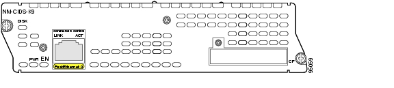
This section provides information on the CIDS network module (NM-CIDS-K9) (see Figure 22-1)
Caution
Figure 22-1 Faceplate for the NM-CIDS-K9 Network Module
Connecting CIDS Network Modules to the Network
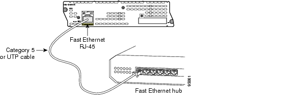
To connect a CIDS network module to the network, use a straight-through two-pair Category 5 unshielded twisted-pair (UTP) cable to connect the RJ-45 port on the CIDS network module to a switch, hub, repeater, server, or other network device. (See Figure 22-2.)
Note
Caution
Figure 22-2 Connecting a CIDS Network Module to a Fast Ethernet Hub
CIDS Network Module LEDs
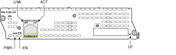
All network modules have an enable (EN) LED. This LED indicates that the module has passed its self-tests and is available to the router.
All CIDS network modules display an additional power (PWR) LED and a CompactFlash (CF) LED on the faceplate, and two additional LEDs for the Fast Ethernet port (see Figure 22-3 and Table 22-1).
Figure 22-3 CIDS Network Module LEDs
Online Insertion and Removal with a CIDS Network Module
Some Cisco modular access routers allow you to replace network modules without switching off the router or affecting the operation of other interfaces. This feature is called online insertion and removal (OIR). OIR of network modules provides uninterrupted operation to network users, maintains routing information, and ensures session preservation.
Caution
Caution
For a description of informational and error messages that may appear on the console during this procedure, see the hardware installation guide for your type of router.
To perform online removal of a CIDS network module and insertion of a replacement, follow these steps with the router in privileged EXEC mode:
Step 1
Router# service-module IDS-Sensor slot/0 shutdownTrying 10.10.10.1, 2129 ... OpenWait for the following status message (it may take a minute or two):
%SERVICEMODULE-5-SHUTDOWN2:Service module IDS-Sensor1/0 shutdown completeStep 2
Step 3
Step 4
Step 5
Note
Step 6
Step 7
Step 8
Step 9
Router#service-module IDS-Sensor slot/0 resetUse reset only to recover from shutdown or failed stateWarning: May lose date on the hard disc!Do you want to reset?[confirm]Step 10
Step 11
Related Documents
For additional information, refer to the following documents.
Tip
Cisco IDS Software Documentation
Tip
For a list of caveats, documentation changes, and important last-minute information for Cisco Intrusion Detection System Version 4.1, see the Release Notes for the Cisco Intrusion Detection System Version 4.1.
For a quick overview of the tasks required to install and initially configure Cisco IDS components, see the Quick Start Guide for the Cisco Intrusion Detection System Version 4.1.
For installation instructions for all Cisco IDS version 4.1 hardware components, including appliances, modules, accessories, and upgrades (such as the IDS XL card), and basic configuration tasks using command line interface (CLI), see the Cisco Intrusion Detection System Appliance and Module Installation and Configuration Guide Version 4.1.
For information on installing and using Cisco IDS Device Manager and Cisco IDS Event Viewer, see the Installing and Using the Cisco Intrusion Detection System Device Manager and Event Viewer Version 4.1.
For IDS CLI reference, including syntax and usage guidelines, see the Cisco Intrusion Detection System Command Reference Version 4.1.
![]()
![]()
![]()
![]()
![]()
![]()
![]()
![]()
Posted: Fri Dec 14 12:06:56 PST 2007
All contents are Copyright © 1992--2007 Cisco Systems, Inc. All rights reserved.
Important Notices and Privacy Statement.