cc/td/doc/product/access/acs_mod/cis2600/hw_inst/nm_inst
hometocprevnextglossaryfeedbacksearchhelp
PDF

Table Of Contents

Connecting T3/E3 Network Modules

1-Port T3/E3 Network Modules

Connecting T3/E3 Network Modules to the Network

T3/E3 Network Module LEDs

Related Documents

Cisco IOS Software Documentation


Connecting T3/E3 Network Modules


This chapter describes how to connect T3/E3 network modules for modular access routers and contains the following sections:

1-Port T3/E3 Network Modules

Connecting T3/E3 Network Modules to the Network

T3/E3 Network Module LEDs

Related Documents


Tip To determine whether your router supports a specific network module, see Table 1-6 on page 1-16.


1-Port T3/E3 Network Modules

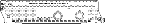
The NM-1T3/E3 network module is a single-port universal T3/E3 network module with integrated CSU/DSU, clear channel, and subrate support. (See Figure 20-1.) Channels on the network module can be configured as either T3 or E3 through Cisco IOS software.

Figure 20-1 1-Port T3/E3 Network Module Faceplate


Note The NM-1T3/E3 network module provides subrate T3 support for Digital Link, Kentrox, Larscom, Verilink, and Adtran. The NM-1T3/E3 network module also provides subrate E3 support for Digital Link and Kentrox.


Connecting T3/E3 Network Modules to the Network

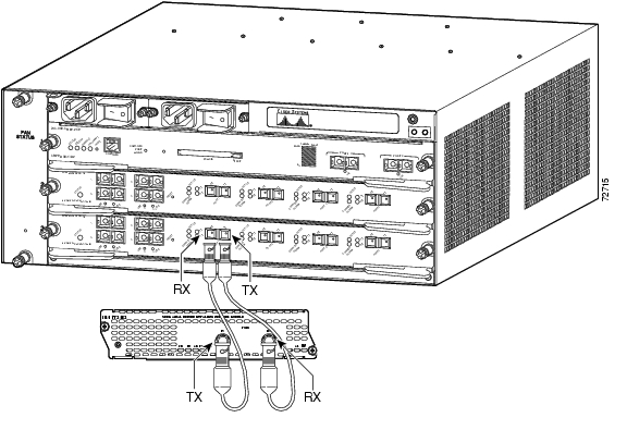
To connect a T3/E3 network module to the network, use a 75-ohm 728-A coaxial cable to connect the BNC connector on the network module to a networking device. (See Figure 20-2.)


Warning This equipment contains a ring signal generator (ringer), which is a source of hazardous voltage. Do not touch the RJ-11 (phone) port wires (conductors), the conductors of a cable connected to the RJ-11 port, or the associated circuit-board when the ringer is active. The ringer is activated by an incoming call. Statement 1042


Warning If the symbol of suitability with an overlaid cross appears above a port, you must not connect the port to a public network that follows the European Union standards. Connecting the port to this type of public network can cause severe injury or damage your router. Statement 1031


Caution To minimize transient surges, the internal wiring should not be routed in the same conduit with power lines or external telephone lines.

Figure 20-2 Connecting a T3/E3 Network Module to a Networking Device (Cisco 7603 Router Shown)


Tip When connecting the T3/E3 network module to a port adapter used in another router series, verify that you are connecting the TX port on the network module with the RX port on the port adapter, and the TX port on the port adapter to the RX port on the network module.


T3/E3 Network Module LEDs

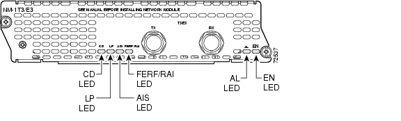
All network modules have an enable (EN) LED. This LED indicates that the module has passed its self-tests and is available to the router. See Figure 20-3 and Table 20-1 for LEDs on the T3/E3 network module.

Figure 20-3 T3/E3 LEDs

Table 20-1 T3/E3 Network Module LEDs 

LED
Meaning

CD

Green indicates that a signal is present on the port.

LP

Yellow indicates that a loopback condition is present on the port.

AIS

Yellow indicates an alarm on the DS3 transmission.

FERF/RAI

Yellow indicates a remote failure at the far end of the connection.

AL

Yellow indicates that the port is out of frame.

EN

Green indicates that the network module has passed self-test and is available to the router.


Related Documents

For additional information, see the following documents.


Tip For information on obtaining documentation, see the "Obtaining Documentation" section on page viii. For information on obtaining technical assistance, see the "Obtaining Technical Assistance" section on page xi.


Cisco IOS Software Documentation

For information on Cisco IOS software features specific to the T3/E3 network module, see the Clear Channel T3/E3 Network Module with Integrated CSU/DSU document.


hometocprevnextglossaryfeedbacksearchhelp

Posted: Fri Dec 14 11:57:29 PST 2007
All contents are Copyright © 1992--2007 Cisco Systems, Inc. All rights reserved.
Important Notices and Privacy Statement.