|
|

Table Of Contents
Connecting High-Density Analog Telephony Network Modules
High-Density Analog Telephony Network Module
Connecting the High-Density Analog Telephony Network Module to the Network
High-Density Analog Telephony Network Module LEDs
High-Density Analog Voice Card Pinouts
Connecting High-Density Analog Telephony Network Modules
This chapter describes how to connect high-density analog telephony network modules for Cisco modular routers. It contains the following sections:
•
High-Density Analog Telephony Network Module
•
•
•
•
•
Tip
High-Density Analog Telephony Network Module
The high-density analog telephony network module is a modular, high-density voice network module that provides dual tone multifrequency (DTMF) detection, voice compression and decompression, call progress tone generation, voice activity detection (VAD), echo cancellation, and adaptive jitter buffering.
The high-density analog telephony network module supports two different expansion modules, providing up to 12 ports in addition to the 4 Foreign Exchange Service (FXS) ports on the base high-density analog telephony network module (NM-HDA). See Table 16-1 for expansion module support information.
Table 16-1 Expansion Modules Supported on the Cisco High-Density Analog Telephony Network Module (NM-HDA)
EM-HDA-8FXS
FXS
8
EM3-HDA-8FXS
FXS
8
EM-HDA-4FXO
FXO
4
EM2-HDA-4FXO
FXO1
4
1 FXO = Foreign Exchange Office
These expansion modules can be used in the following combinations:
•
•
•
The FXO expansion module supports a power failure port that connects directly to the central office (CO) in case of failure. Physical ports are added as shown in Table 16-2.
Tip
The digital signal processors (DSPs) on the card support up to 8 ports of high-complexity codecs or up to 16 ports of medium- and low-complexity codecs. The number of DSPs must be increased if more than eight ports of high-complexity codecs are needed. In this case, a DSP expansion module must be installed.
The high-density analog telephony network module is connected to the network using an RJ-21 Amphenol connector on the front panel. The front of the card is shown in Figure 16-1.
Figure 16-1 High-Density Analog Telephony Network Module
Connecting the High-Density Analog Telephony Network Module to the Network
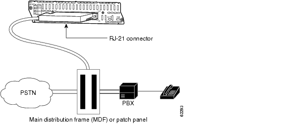
The high-density analog telephony network module is connected to a distribution frame with an RJ-21 cable. (See Figure 16-2.) RJ-21 cables are not provided with the network module. Some recommended cables are as follows:
•
•
For ordering information, see the "Obtaining Technical Assistance" section on page xi.
Figure 16-2 High-Density Analog Telephony Card Connected to a Main Distribution Frame
Adding DSP Expansion Modules
DSP expansion modules can be used if more than eight ports using high-complexity codecs are needed on the high-density analog telephony network module.
To install DSP expansion modules, follow these steps:
Step 1
Note
Step 2
Step 3
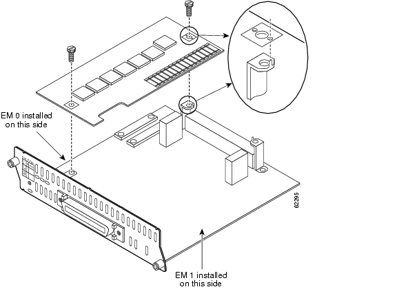
Figure 16-3 Installing a DSP Expansion Module
Adding Port Expansion Modules
Port expansion modules can be used to increase the number of ports supported on the high-density analog telephony network module.
To install port expansion modules, follow these steps:
Step 1
Step 2
Note
Caution
Step 3
Warning
Figure 16-4 Installing a Port Expansion Module
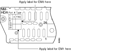
Step 4
Step 5
Figure 16-5 Label Locations for Expansion Ports
High-Density Analog Telephony Network Module LEDs
Figure 16-6 shows high-density analog telephony network module LEDs. Table 16-3 describes their meaning.
Figure 16-6 High-Density Analog Telephony Network Module LEDs
High-Density Analog Voice Card Pinouts
Figure 16-7 shows the RJ-21 connector wiring for the cable used for the high-density analog voice card; Table 16-4 lists the pinouts. The port usage depends on the type of expansion cards installed.
Figure 16-7 RJ-21 Connector Wiring
![]()
![]()
![]()
![]()
![]()
![]()
![]()
![]()
Posted: Fri Dec 14 11:55:43 PST 2007
All contents are Copyright © 1992--2007 Cisco Systems, Inc. All rights reserved.
Important Notices and Privacy Statement.