|
|

Table Of Contents
Connecting Wireless Multipoint Network Modules
Wireless Multipoint Network Modules
Hardware and Software Requirements
Connecting Wireless Ports to the Network
Wireless Multipoint Network Module LEDs
Connecting Wireless Multipoint Network Modules
This chapter explains how to connect the wireless multipoint network module and contains the following sections:
•
Wireless Multipoint Network Modules
•
•
•
Tip
Wireless Multipoint Network Modules
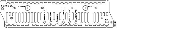
The wireless multipoint network module, shown in Figure 15-1, also referred to as a subscriber unit (SU), provides a high-speed broadband fixed wireless radio-frequency (RF) link between each subscriber site and a single headend site. This link delivers full-duplex data in the licensed MMDS band (2.500 to 2.690 GHz) or unlicensed U-NII band (5.725 to 5.825 GHz).
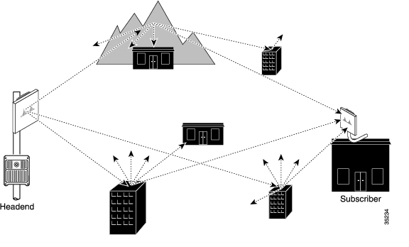
The headend of the system consists of a Cisco uBR7200 series universal broadband router, one or more wireless modem cards, and the required subsystem for each modem card. The diversity option, which minimizes the effects of fading, uses two wireless transverters at each site, with each transverter connected to its own antenna. (See Figure 15-2.)
Figure 15-1 Wireless Multipoint Network Module with Diversity
Figure 15-2 Multipoint Communications with Multipath and Diversity Reception
The network module provides the control and data interface to the radio frequency (RF) subsystem in the wireless transverter. It also provides the up-down conversion from baseband to intermediate frequency (IF). One network module supports one or two wireless transverters (main and diversity).
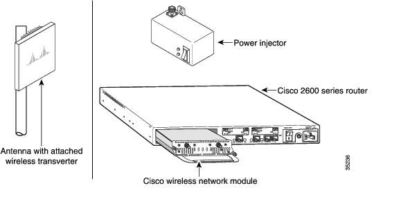
Subscriber-Unit System
Each subscriber unit system (see Figure 15-3) consists of the necessary cables and these items:
•
•
•
•
Figure 15-3 Components of the Multipoint Subscriber-Unit System
Note
Hardware and Software Requirements
Wireless multipoint network modules require that the router have at least 16 MB of flash memory.
The wireless multipoint network modules require an external microcode bundle. You can download this microcode at http://www.cisco.com/cgi-bin/tablebuild.pl/rsu.
Connecting Wireless Ports to the Network
Use an indoor IF coaxial cable to connect the wireless network module Main connector to a power injector. If you are using the diversity feature, connect the network module Diversity connector to a second power injector.
Wireless Multipoint Network Module LEDs
Wireless multipoint network modules have the LEDs shown in Table 15-1.
Related Documents
For additional information, see the following documents.
Subscriber Unit
•
Headend
•
•
•
•
•
•
![]()
![]()
![]()
![]()
![]()
![]()
![]()
![]()
Posted: Fri Dec 14 11:57:59 PST 2007
All contents are Copyright © 1992--2007 Cisco Systems, Inc. All rights reserved.
Important Notices and Privacy Statement.