|
|

Table Of Contents
Connecting Ethernet Switch Network Modules
Ethernet Switch Network Modules
Requirements for Installing Two Ethernet Switch Network Modules in a Single Chassis
Restrictions for Cisco 3700 Series Routers
Restrictions for Cisco 2600 Series and Cisco 3600 Series Routers
Connecting the Ethernet Switch Network Module to the Network
Adding an Optional Gigabit Ethernet Expansion Board
Adding an Optional Power Board
Ethernet Switch Network Module LEDs
Connecting Ethernet Switch Network Modules
This chapter describes how to connect Ethernet switch network modules and contains the following sections:
•
Ethernet Switch Network Modules
•
•
•
•
•
Tip
Ethernet Switch Network Modules
This chapter explains how to install the 16- and 36-port Ethernet switch network modules. The Ethernet switch network module is a modular, high-density voice network module that provides Layer 2 switching across Ethernet ports. The 16-port Ethernet switch network module has 16 10/100BASE-TX ports and an optional 10/100/1000BASE-T Gigabit Ethernet port. The 36-port Ethernet switch network module has 36 10/100BASE-TX ports and 2 optional 10/100/1000BASE-T Gigabit Ethernet ports. The 36-port Ethernet switch network module requires a double-wide slot. An optional power module can also be added to provide inline power for IP telephones.
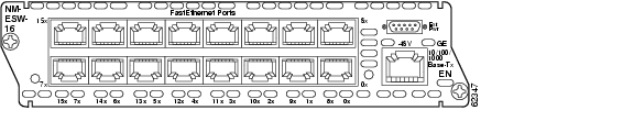
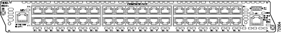
The10/100BASE-TX ports and Gigabit Ethernet ports on the Ethernet switch network module are connected to the network using RJ-45 connectors on the front panel. The power module is connected to an external power supply using a power connection cable. The front of the 16-port card is shown in Figure 17-1. The front panel of the 36-port card is shown in Figure 17-2.
Figure 17-1 16-Port Ethernet Switch Network Module
Figure 17-2 36-Port Ethernet Switch Network Module
Requirements for Installing Two Ethernet Switch Network Modules in a Single Chassis
A maximum of two Ethernet switch network modules can be installed in a single chassis. If two Ethernet switch network modules of any type are installed in the same chassis, the following configuration requirements must be met:
•
•
•
Without this configuration and connection, duplications will occur in the VLAN databases, and unexpected packet handling may occur.
Power Considerations
The Ethernet switch network module supports inline powering of IP telephones with -48-V power. This allows IP phones to be plugged into the standard RJ-45 jack and be powered from this source rather than having a separate plug into an AC wall outlet. The Ethernet switch network module requires delivery of -48-V power to the network module in order to provide inline powering of IP telephones.
Cisco 2800 series, Cisco 3700 series, and Cisco 3800 series routers supply -48 V power internally (with AC-IP power supplies) to the Ethernet switch service modules. To support Cisco 2600 series and Cisco 3600 series routers, which do not supply -48-V internal power, the network module has an external connector for connection to an external -48-V power supply.
The Ethernet switch network module distributes the -48-V power to each of the Ethernet ports that are configured for line power. Each port can be independently configured for line power.
Note
Restrictions for Cisco 3700 Series Routers
Cisco 3700 series routers contain internal -48-V power supplies to supply power to the Ethernet switch network module.
For the Cisco 3745 router, the following specifications apply:
•
•
•
Cisco 3725 routers have a single -48-V supply. Cisco 3725 routers do not report any power supply status. The only software indication of -48-V status is the -48-V status bit provided on the 16-port Ethernet switch network module board.
Restrictions for Cisco 2600 Series and Cisco 3600 Series Routers
Cisco 2600 series and Cisco 3600 series routers do not supply -48-V power, so an external -48-V supply is required to support inline power for IP phones. This external power supply connects to the Ethernet switch network module faceplate with a cable.
An external power supply plugged into an Ethernet switch network module provides power only for that specific network module. To supply redundant power, a Y cable can be used so that two external power supplies are connected to the same card.
For more information about external power supplies, see the Cisco External Power Supply for Cisco Ethernet Switch Network Modules Installation Guide.
Connecting the Ethernet Switch Network Module to the Network
Warning
The Ethernet switch network module is connected to an Ethernet switch or hub with RJ-45 cables. (See Figure 17-3.) RJ-45 cables are not provided with the network module. For ordering information, see the "Obtaining Technical Assistance" section on page xi.
Note
Tip
http://www-tac.cisco.com/Support_Library/Hardware/LAN_Switches_and_
Modules/Cat6000/Troubleshooting/QuickTip.998950447.htmlFigure 17-3 16-Port Ethernet Switch Card Connected to Ethernet Switch or Hub
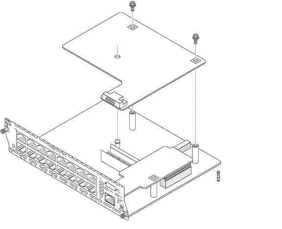
Adding an Optional Gigabit Ethernet Expansion Board
An optional Gigabit Ethernet expansion board can be installed to support a 10/100/1000BASE-T Gigabit Ethernet port.
To install a Gigabit Ethernet expansion board, follow these steps:
Step 1
Figure 17-4 Gigabit Ethernet Board Port Cover on the Ethernet Switch Network Module
Step 2
Step 3
Caution
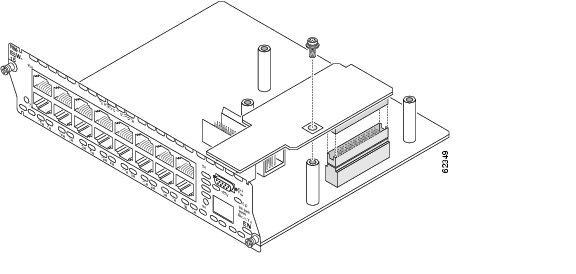
Step 4
Figure 17-5 Installing a Gigabit Ethernet Expansion Board on a 16-Port Cisco Ethernet Switch Network Module
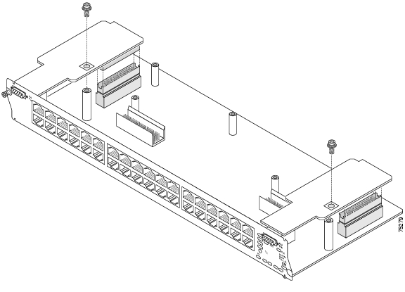
Figure 17-6 Installing a Gigabit Ethernet Expansion Board on a 36-Port Cisco Ethernet Switch Network Module
Adding an Optional Power Board
An optional power board can be used if the Ethernet switch network module requires external -48-V power for IP telephones. Installation and configuration of the external power supply system is described in the Cisco External Power Supply for Cisco Ethernet Switch Network Modules Installation Guide.
To install power boards, follow these steps:
Step 1
Figure 17-7 Power Board Port Cover on the Ethernet Switch Network Module
Step 2
Step 3
Step 4
Note
Step 5
Step 6
Warning
Step 7
Figure 17-8 Installing a Power Board in a 16-Port Ethernet Switch Network Module
Figure 17-9 Installing a Power Board in a 36-Port Ethernet Switch Network Module
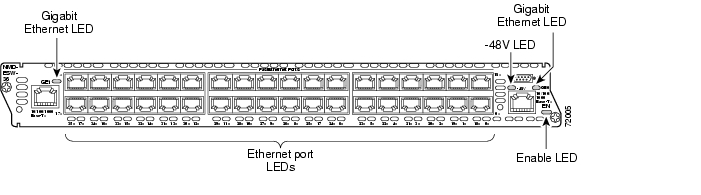
Ethernet Switch Network Module LEDs
Figure 17-10 shows 16-port Ethernet switch network module LEDs. Figure 17-11 shows 36-port Ethernet switch network module LEDs. Table 17-1 describes their meaning.
Figure 17-10 16-Port Ethernet Switch Network Module LEDs
Figure 17-11 36-Port Ethernet Switch Network Module LEDs
![]()
![]()
![]()
![]()
![]()
![]()
![]()
![]()
Posted: Fri Dec 14 11:57:56 PST 2007
All contents are Copyright © 1992--2007 Cisco Systems, Inc. All rights reserved.
Important Notices and Privacy Statement.