|
|

This chapter contains information on maintenance procedures you might do as your internetworking needs change.
This chapter contains the following sections:
This chapter also contains descriptions of system card jumper settings.
 | Caution Before opening the chassis, ensure that you have discharged all static electricity from your body and be sure the power is OFF. Before performing any procedures described in this chapter, review the following sections in Chapter 2: "Safety Recommendations," "Safety with Electricity," "Preventing Electrostatic Discharge Damage," and "Tools and Equipment Required." |
The following tools are required for the procedures described in this chapter:
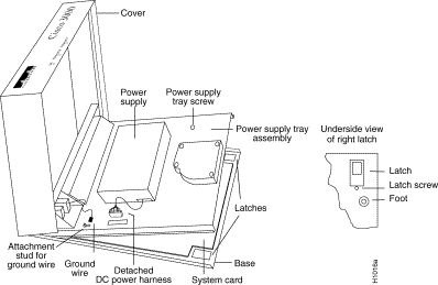
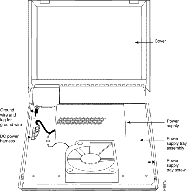
You must open the router chassis to gain access to its interior components: the system card, Flash SIMMs, Flash EPROMs, DRAM SIMMs, boot ROMs, and jumpers. This section outlines the steps required to open the router chassis. Figure 5-1 shows the internal components of the router. When performing the cover and the power-supply tray assembly removal procedures, have the router face you. (Use Figure 5-2 as a guide.)
After you take the necessary ESD precautions, you can proceed with opening the chassis.
 | Warning Hazardous voltages may exist in or near the power supply, so use extreme caution when working near the power supply. Before starting any of these procedures, turn OFF power to the system, unplug the power cord, disconnect any cables at the ports, and connect ESD protection. |
To remove the chassis cover, follow these steps.
Step 1 Turn OFF the unit and unplug it.
Step 2 Attach ESD protection.
Step 3 Remove all cables from the back of the router (including the power cable) to ensure that the unit is not powered on and to ensure that the cover will not get caught on the cables.
 | Caution Avoid damaging any cables as you remove the cover. |
Step 4 Turn the unit up so that the back of the chassis is resting on a surface, and the underside of the chassis is facing you, taking care not to damage the network connectors.
Step 5 Remove the latch screw (shown in Figure 5-1) behind the latch on the right side of the underside of the chassis. The latch will not open until this screw is removed.
Step 6 Put the unit back down with the LEDs facing you. Place your fingers inside the two front latches on the underside of the chassis (see Figure 5-1) and push the latches back until they snap open.
Step 7 Lift the chassis cover from the front edge where the LEDs are located. The chassis cover will tilt up from the front toward the back. If you feel excessive resistance when opening the unit, one of the latches might still be closed. Push back on the latches again.
Step 8 Remove the ground wire (green with yellow stripes) connecting the left hinge post on the cover with the main ground stud, as shown in Figure 5-2. The ground wire is attached to the main ground stud with a slip-on lug, so the wire can be slipped off easily.
Step 9 Remove the chassis cover the rest of the way by pulling it up and forward so that the hinge posts come free from the notches in the bottom tray.
Step 10 Set the cover aside.
To access the router system card, you must remove the router power- supply tray assembly as follows:
Step 1 Locate the DC power harness on the far left edge of the power-supply tray assembly. (See Figure 5-2.) Detach the DC power harness from the system card under the power-supply tray assembly using the pull tab provided.
 | Caution If you lift the power-supply tray assembly without first removing the power-supply harness, you might damage the cable which provides all power to the system card. |
Step 2 Remove the power-supply tray screw.
Step 3 Place your fingers underneath the front edge of the power-supply tray assembly and pull the edge up. The latches holding the power-supply tray assembly will release.
Step 4 Slide the power-supply tray assembly toward you, lift it off the base, and remove it. The system card is now exposed. You do not need to remove the system card from the base of the chassis.
Step 5 Set the power-supply tray assembly aside.
Table 5-1 lists the interface ports on the various router models.
| Model | Ethernet | Token Ring | Serial | BRI |
|---|---|---|---|---|
| 3101 (See Figure 5-5)1 | 2 | 0 | 0 | 0 |
| 3102 (See Figure 5-5) | 1 | 0 | 1 | 0 |
| 3103 (See Figure 5-5) | 1 | 0 | 0 | 1 |
| 3202 (See Figure 5-7) | 0 | 1 | 1 | 0 |
| 3104 (See Figure 5-4) | 1 | 0 | 2 | 1 |
| 3204 (See Figure 5-3) | 0 | 1 | 2 | 1 |
Refer to the appropriate figure to determine your system's jumper locations.
Figure 5-3 shows the jumper locations at J11 and J12 on the model 3204 system card, and it shows the jumpers' labels. Jumper location J1 enables or disables the writing to Flash memory.
Jumper location J12 is set according to the size of the boot ROMs.
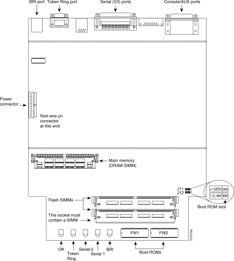
Figure 5-4 shows the jumper locations at J11 and J12 on the model 3104 system card, and it shows the jumpers' labels. Jumper location J11 enables or disables the writing to Flash memory.
Jumper location J12 is set according to the size of the boot ROMs.
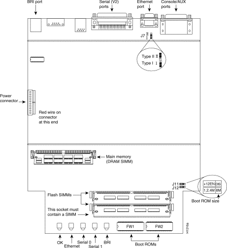
Figure 5-5 shows the jumper locations W1, W3, and W4 on the model 3101 system card, and it shows the labels of the jumpers.
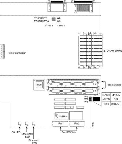
Using the orientation of Figure 5-6, jumper location W1 (see Figure 5-6) ships with its left two pins jumpered together. At location W3, jumper the two left pins to permit writing to Flash memory, or jumper the two right pins to disable writing to Flash memory. At location W4, the two pins are jumpered to the corresponding size of the boot ROM memory.
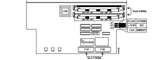
Figure 5-7 shows the jumper locations W1, W2, W3, and W4 on the model 3202 system card with Token Ring and serial interfaces, and it shows the labels of the jumpers.
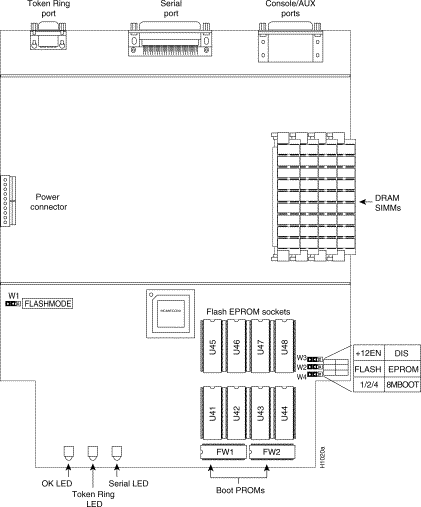
Using the orientation of Figure 5-7 for the model 3202 default jumper locations, note that W1 ships with its left two pins jumpered together. At location W3, the two left pins are jumpered to permit writing to Flash memory, or the two right pins are jumpered to disable writing to Flash memory. At location W4, the jumper corresponds to the size of boot ROM memory as shown on the ROM labels.
Figure 5-8 shows the correct jumper setting for jumper location W1 on the model 3202 when the system card is oriented as in Figure 5-7. There should be no normal conditions under which the jumper setting on W1 should be changed.

For information on configuring your system's Flash memory, refer to the Router Products Configuration and Reference publication.
The router contains primary (main memory) and secondary (shared) memory. Both primary and secondary memory size, in kilobytes (KB), are shown in the system banner on the console screen. Primary memory is implemented with dynamic random-access memory (DRAM) single in-line memory modules (SIMMs). Secondary memory, used for packet buffering, consists of a fixed 512 KB (2 megabytes [MB] for models 3104 and 3204).
After booting up, your system will indicate in the system banner the amount of memory it has. The following example shows a system with 4096 KB (4 MB) of primary memory.
System Bootstrap, Version 4.6(0.15), SOFTWARE
Copyright (c) 1986-1992 by cisco Systems
Cisco 3000/030 processor with 4096 Kbytes of memory
>
Primary memory may need to be expanded when you use very large routing tables or many protocols. This might be necessary with configurations in which the router is set up as a connection device between large external networks and your internal network.
The standard primary memory (main memory) configuration of the router models 3101, 3102, 3103, and 3202 are 4 MB of 32-bit-wide DRAM. Upgrade to 16 MB of 32-bit-wide DRAM by replacing the system's four 1 MB x 9 SIMMs. For 16-MB configurations, substitute four 4 MB x 9 DRAM SIMMs.
Memory upgrade kits for the router include four new 4 MB x 9 DRAM SIMMs.
Table 5-2 lists approved 4 MB x 9, 80-nanosecond DRAM SIMMs for models 3101, 3102, 3103, and 3202.
| Manufacturer's Name | Manufacturer's Part Number |
|---|---|
| Motorola | MCM94000AS80 |
| Micron | MT9D49M-8 |
| Texas Instruments | TM100EAD9-80 |
After booting up, your system will indicate in the system banner the amount of primary and secondary memory it has. The following example shows a system with 4096 KB (4 MB) of primary memory and 512 KB (1/2 MB) of secondary memory:
System Bootstrap, Version 9.1 ROUTER SOFTWARE
Copyright (c) 1986-1992 cisco Systems, Inc.
Cisco 3000/030 processor with 4608 Kbytes of memory
>
The standard primary memory configuration of the router models 3204 and 3104 are 4 MB and
8 MB. You can upgrade from 4 MB of DRAM (main memory) by replacing the 72-pin DRAM SIMM in the main memory socket on the system card. Memory upgrade kits for the router models 3204 and 3104 are obtainable from us. Table 5-3 lists approved 2 MB x 36, 80-nanosecond DRAM SIMMs for models for models 3204 and 3104.
| Manufacturer's Name | Manufacturer's Part Number |
|---|---|
| Micron | MT18D236M-8 |
| NEC | MC-422000A36B-80 |
You can upgrade your router, models 3204 and 3104, from the standard 4 MB of primary memory to 8 MB (see Table 5-3) using the memory upgrade kit as follows:
Step 1 Turn OFF the unit and unplug it.
Step 2 Attach ESD protection.
Step 3 Open the cover according to the procedures in the sections "Opening the Chassis" and "Removing the Power-Supply Tray Assembly."
Step 4 Locate the primary memory (DRAM SIMMs) by using Figure 5-3 or Figure 5-4.
Step 5 Remove the existing DRAM SIMMs by pulling outward on the connectors to unlatch them, as shown in Figure 5-9. Be careful not to break the holders on the SIMM connector.
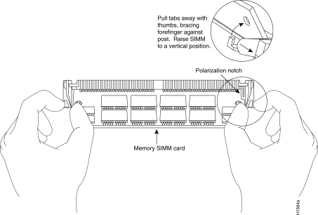
Step 6 Insert the new DRAM SIMM into the open connector by sliding the end with the metal fingers into the DRAM SIMM connector socket, at approximately a 45-degree angle to the system card. Gently rock the DRAM SIMM back into place until the latch on either side snaps into place. Do not use excessive force, or the connector could break.
Step 7 Reassemble the router following the procedures in the section "Replacing the Chassis Cover and Tray," taking care not to pinch the DC power harness.
Step 8 Connect the router to a console terminal and turn On the power. If error messages relating to memory are displayed, repeat steps 1 through 6, taking care to firmly seat the SIMM in its socket.
You can upgrade your router, models 3101, 3102, 3103, and 3202 from the standard 4 MB of primary memory to 16 MB using the memory upgrade kit as follows:
Step 1 Turn OFF the unit and unplug it.
Step 2 Attach ESD protection.
Step 3 Open the cover according to the procedures in the sections "Opening the Chassis" and "Removing the Power-Supply Tray Assembly."
Step 4 Locate the DRAM SIMMs by using Figure 5-5 or Figure 5-7.
Step 5 Remove the existing DRAM SIMMs by pulling outward on the connectors to unlatch them, as shown in Figure 5-9. Be careful not to break the holders on the SIMM connector.
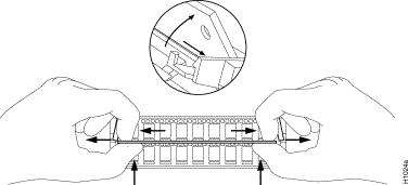
Step 6 Plug each new DRAM SIMM (4 MB x 9) into the open connector. To insert a new DRAM SIMM card, slide the end with the metal fingers straight down into the SIMM connector socket, at an angle perpendicular to the card. Gently rock the DRAM SIMM back toward the SIMMs already installed and snap into place. Do not use excessive force, or the connector could break.
Step 7 Repeat step 5 for each new DRAM SIMM card.
Step 8 Reassemble the router following the procedures in the section "Replacing the Chassis Cover and Tray," taking care not to pinch the DC power harness.
Step 9 Connect the router to a console terminal and turn ON the power. If error messages relating to memory are displayed, repeat steps 1 through 7, taking care to firmly seat the DRAM SIMMs in their sockets.
80-pin Flash memory SIMMs can be purchased from us or from other vendors.
If you are replacing Flash memory with SIMMs you purchase from other vendors, be sure to use 120-nanosecond memory Flash SIMMs from the vendor listed in Table 5-4.
| Manufacturer's Name | Manufacturer's Part Number |
|---|---|
| SMART Module | SM732C1024.12 |
The procedures for replacing Flash Memory SIMMs require the tools and equipment following:
Follow these steps to upgrade the Flash memory on all models except 3202, which employs Flash EPROMs:
Step 1 Turn OFF the router and unplug it.
Step 2 Open the chassis cover according to the procedures in the sections "Opening the Chassis" and "Removing the Power-Supply Tray Assembly."
Step 3 Locate the Flash memory SIMMs on the system card. (Shown in Figure 5-3, Figure 5-4, and Figure 5-5.)
Step 4 Gently spread the Flash memory SIMM connector holddowns until they are wide enough to permit you to remove the Flash memory SIMM. (See Figure 5-11.)
Step 5 Repeat for all the Flash memory SIMMs to be replaced.
 | Caution Do not push on the Flash chips themselves. Handle the Flash SIMM and its components with care. They are fragile. |
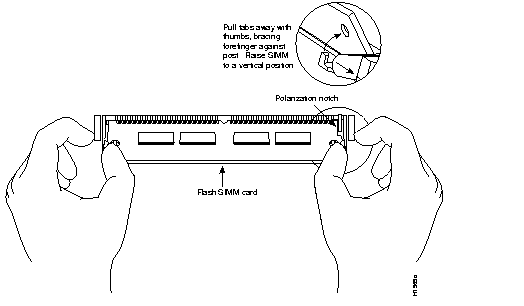
Step 6 Plug the new Flash memory SIMM into the open connector. To insert a new SIMM, slide the end with the metal fingers straight down into the SIMM connector socket, at an angle perpendicular to the system card. Gently rock the SIMM back toward the SIMMs already installed and snap into place. Do not use excessive force, or the connector could break.
After opening the model 3202 chassis to access the system card, follow the procedures in this section to replace the Flash EPROMs.
After removing the old EPROMs, keep them separate from the new ones to avoid mixing the two sets.
 | Caution The correct placement of the Flash EPROMs is crucial. If improperly positioned, the EPROMs could be damaged when the system is powered on. Read through all of the instructions before proceeding. To prevent damage to the EPROMs from electrostatic discharge (when handling the system and its components) be sure to follow the ESD procedures described in Chapter 2. Also, be careful not to damage or scratch the printed circuit card under the EPROMs. |
In addition to the tools listed in the section "Tools and Equipment Required for Flash Memory SIMM Replacement," you need the following tools and equipment to install Flash EPROMs in the model 3202:
Figure 5-7 illustrates the model 3202 card layout. The card is oriented with the front panel LEDs at the bottom of the illustration. Refer to this figure to locate the EPROMs on the system card.
Follow these steps to install Flash memory EPROMs in the model 3202:
Step 1 Locate the EPROMs labeled U41 through U48 at the front of the unit. (See Figure 5-7.) Note the orientation of the notches on the EPROMs to aid in inserting the new EPROMs. Do not rely on the EPROM labels for correct positioning.
Step 2 Use an EPROM removal tool to gently remove EPROMs U41 through U48. Set the EPROMs aside and keep them in case you need to use them again.
Step 3 Insert the new EPROMs in the sockets U41 through U48 in the order shown in Figure 5-7, being careful not to bend or crush any of the pins. To straighten out a bent pin, use needlenose pliers. Align the notch in the EPROM with the notch in the EPROM socket, ignoring the orientation of the label. Be sure to insert the new EPROMs using the same orientation as the EPROMs you are replacing.
To replace the boot ROM software with a new software image, the existing boot ROMs must be replaced.
The following tools and equipment are required to replace the boot ROMs:
Follow this procedure to replace the boot ROMs:
Step 1 To open the chassis and expose the boot ROMs, follow the procedures in the sections "Opening the Chassis" and "Removing the Power-Supply Tray Assembly."
Step 2 Once the boot ROMs, FW1 and FW2, on the system card are exposed, follow the procedures in this section to replace the ROMs.
 | Caution The correct placement of the boot ROMs is crucial. If improperly positioned, the new components could be damaged when the system is powered on. Read through all of the instructions before proceeding. To prevent damage to the ROMs from ESD (when handling the system and its components), follow the ESD procedures described earlier. Also, be careful not to damage or scratch the printed circuit card under the ROMs. |
Step 3 Locate the boot ROMs, FW1 and FW2. (See Figure 5-3, Figure 5-4, Figure 5-5, and Figure 5-7.)
Step 4 Using an EPROM extraction tool or a small flat-blade screwdriver, gently remove the boot ROMs and set them aside.
Step 5 Insert the new boot ROMs in their respective sockets in the orientation shown in Figure 5-3, Figure 5-4, Figure 5-5, and Figure 5-7, being careful not to bend or crush any of the bottom pins. To straighten out a bent pin, use needlenose pliers. Align the notch in the new ROM with the notch in the ROM socket, ignoring the orientation of the label.
After you perform the maintenance for your system, replace the cover and component tray by following these steps.
Step 1 Replace the metal power supply and tray assembly on the chassis.
Step 2 Replace the power-supply tray screw. (See Figure 5-2.)
Step 3 Replace the ground wire by connecting the ground wire to the stud.
Step 4 Replace the DC power harness. (See Figure 5-2.)
Step 5 Replace the chassis cover.
Step 6 Replace the latch screw. (See Figure 5-1.)
Step 7 Replace the chassis cables.
An overview to recovering a lost password follows:
To recover a lost password, follow this procedure:
Step 1 Attach an RS-232 ASCII terminal to the router console port which is located at the rear of the router.
Step 2 Configure the terminal to operate at 9600 baud, 8 data bits, no parity, 1 stop bit (or to whatever settings the router is set).
Step 3 Enter the command show version to display the existing configuration register value. Note this value for later use in step 14.
Step 4 If Break is disabled, power cycle the router. (Turn the router OFF, wait 5 seconds, and then turn it ON again.) If Break is enabled on the router, send a Break and then proceed to step 5.
Step 5 Within 60 seconds of turning the router on, press the Break key. This action causes the terminal to display the bootstrap program prompt (>).
Step 6 To reset the configuration register to boot from the boot ROMs, enter o/r at the bootstrap prompt as follows:
o/r
Step 7 Initialize the router by entering the i command as follows:
i
The router will power cycle, the configuration register will be set to 0x141, and the router will boot the boot ROM system image and prompt you with the system configuration dialog as in the follows:
--- System Configuration Dialog ---
Step 8 Enter no to the system configuration dialog prompts until the following system message is displayed:
Step 9 Press Return. The boot ROM prompt appears as follows:
Step 10 Enter the enable command to enter the EXEC mode in the boot ROM image. The prompt changes to the following:
Step 11 Enter the show configuration EXEC command to display the enable password in the router's configuration file.
Step 12 Enter the configure terminal command at the EXEC prompt. You are prompted as follows:
conf
Step 13 Using the config-reg 0xvalue command, change the configuration register value back to its original value (from step 3) or change it to a value of 0x102, which in the absence of a boot system command in the configuration file, causes the router to boot from Flash memory.
Step 14 Exit configuration mode by entering Ctrl-Z.
Step 15 Reboot the router and enable using the recovered password.
|
|