|
|

This appendix provides the following pinouts for constructing your own cables:
The cables available from Cisco meet FCC part 15J Class A requirements and Verband Deutscher Electrotechniker (VDE) 0871 Limit B levels. When constructing your own cables, refer to the appropriate documentation regarding interference considerations and cable length limitations.
When assembling your own cables, follow these steps:
Step 1 Fold back the braided shield to make electrical and mechanical connection with the metal shell on both ends.
Step 2 Cut unterminated wires back. Insulate or ensure insulation from other conductors.
Step 3 Use the following illustrations and connection tables as a guide to making your own cables:
Refer to Table A-1 when assembling an RS-232 console cable, and refer to Table A-2 when assembling an RS-232 auxiliary port cable.
| Pin1 | Signal Name | Direction |
|---|---|---|
| 1 | Frame Ground | - |
| 2 | Transmitted Data | Input |
| 3 | Received Data | Output |
| 4 | Request To Send | Shorted together internally with Pin 5 |
| 5 | Clear To Send | - |
| 6 | Shorted to Pin 8 | Output |
| 7 | Ground | - |
| 8 | Carrier Detect | Output |
| 20 | Data Terminal Ready | Input |
| Pin2 | Signal Name | Direction |
|---|---|---|
| 1 | Frame Ground | - |
| 2 | Transmitted Data | Output |
| 3 | Received Data | Input |
| 4 | Request To Send | Output |
| 5 | Clear To Send | Input |
| 7 | Ground | - |
| 8 | Carrier Detect | Input |
| 20 | Data Terminal Ready | Output |
| 22 | Ring Indicator | Input |
The following illustrations and tables provide the pinouts and signal descriptions for the RS-232,
RS-449, V.35, X.21, and EIA-530 DTE and DCE cables.
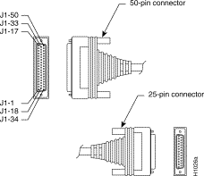
Figure A-1 shows the RS-232 cable assembly. Table A-3 lists the DTE cable pinouts, and
Table A-4 lists the DCE cable pinouts and signal descriptions.
| 72-0670-01 Connections3 | ||
|---|---|---|
| 50 Pin | 25 Pin | Type |
| J1-3 | J1-36 | |
| J1-39 J1-40 | J2-5 J2-4 | Twisted Pair |
| J1-9 J1-42 | J2-8 J2-6 | Twisted Pair |
| J1-11 J1-44 | J2-2 J2-7 | Twisted Pair |
| J1-46 J1-30 | J2-3 J2-20 | Twisted Pair |
| J1-14 J1-47 | J2-18 J2-17 | Twisted Pair |
| J1-31 J1-15 | J2-15 J2-1 | Twisted Pair |
| J1-16 | J2-24 | Twisted Pair |
| 72-0736-01 Connections4 | |||
|---|---|---|---|
| 50 Pin | 25 Pin | Signal | Type |
| J1-3 | J1-36 | MUX | |
| J1-47 J1-17 | J2-24 J1-38 | SCTE DCE | Twisted Pair |
| J1-40 J1-39 | J2-5 J2-4 | CTS RTS | Twisted Pair |
| J1-14 J1-30 | J2-8 J2-6 | DCD DSR | Twisted Pair |
| J1-46 J1-44 | J2-2 J2-7 | TXD GND | Twisted Pair |
| J1-11 J1-42 | J2-3 J2-20 | RXD DTR | Twisted Pair |
| J1-9 J1-23 | J2-18 J2-17 | LTST RXC | Twisted Pair |
| J1-16 J1-15 | J2-15 J2-1 | TXC Chassis Ground | Twisted Pair |
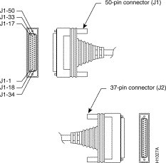
Figure A-2 shows the RS-449 cable assembly. Table A-5 lists the DTE cable pinouts, and
Table A-6 lists the DCE serial cable pinouts and signal descriptions.
| 72-0672-01 Connection Table | ||
|---|---|---|
| 50 Pin1 | 37 Pin | Type |
| J1-5 | J1-38 | |
| J1-7 | J2-10 | |
| J1-1 J1-34 | J2-4 J2-22 | Twisted Pair |
| J1-2 J1-18 | J2-5 J2-23 | Twisted Pair |
| J1-35 J1-19 | J2-6 J2-24 | Twisted Pair |
| J1-4 J1-20 | J2-7 J2-25 | Twisted Pair |
| J1-37 J1-21 | J2-8 J2-26 | Twisted Pair |
| J1-22 J1-6 | J2-27 J2-9 | Twisted Pair |
| J1-8 J1-24 | J2-11 J2-29 | Twisted Pair |
| J1-41 J1-25 | J2-12 J2-30 | Twisted Pair |
| J1-10 J1-26 | J2-13 J2-31 | Twisted Pair |
| J1-43 J1-27 | J2-17 J2-35 | Twisted Pair |
| J1-36 J1-15 | J2-19 J2-1 | Twisted Pair |
| J1-44 J1-48 | J2-37 J2-20 | Twisted Pair |
| 72-0738-01 Connection Table | |||
|---|---|---|---|
| 50 Pin1 | 37 Pin | Type | Signal Name |
| J1-5 | J1-38 | MUX | |
| J1-13 | J2-10 | LL | |
| J1-35 J1-19 | J2-4 J2-22 | Twisted Pair | TXD+ TXD- |
| J1-43 J1-27 | J2-5 J2-23 | Twisted Pair | SCT+ SCT- |
| J1-1 J1-34 | J2-6 J2-24 | Twisted Pair | RXD+ RXD- |
| J1-6 J1-22 | J2-7 J2-25 | Twisted Pair | RTS+ RTS- |
| J1-49 J1-50 | J2-8 J2-26 | Twisted Pair | SCR+ SCR- |
| J1-17 | J1-44 | DCE | |
| J1-20 J1-4 | J2-27 J2-9 | Twisted Pair | CTS- CTS+ |
| J1-41 J1-25 | J2-11 J2-29 | Twisted Pair | DSR+ DSR- |
| J1-8 J1-24 | J2-12 J2-30 | Twisted Pair | DTR+ DTR- |
| J1-10 J1-26 | J2-13 J2-31 | Twisted Pair | RLSD+ RLSD- |
| J1-37 J1-21 | J2-17 J2-35 | Twisted Pair | SCTE+ SCTE- |
| J1-36 J1-15 | J2-19 J2-1 | Twisted Pair | Ground Chassis Ground |
| J1-44 J1-48 | J2-37 J2-20 | Twisted Pair | Ground Ground |
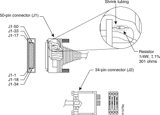
Figure A-3 shows the V.35 cable assembly with the resistor (301 ohms, 1/4 watt, ±1%), and Table A-7 and Table A-8 list the V.35 cable pinouts and signal descriptions.
| 72-0671-02 Connections | ||||
|---|---|---|---|---|
| 50 Pin1 | 34 Pin | Type | Signal | Direction |
| J1-3 | J1-36 | Jumper | MUX | To Ground |
| J1-5 | J1-38 | Jumper | MUX | To Ground |
| J1-14
J1-Shield | J2-K J2-Shield | Twisted Pair | LTST Not Used |  |
| J1-2 J1-18 | J2-Y J2-AA | Twisted Pair | SCT+ SCT- |  |
| J1-12 J1-28 | J2-P J2-S | Twisted Pair | TXD+ TXD- |   |
| J1-35 J1-19 | J2-R J2-T | Twisted Pair | RXD+ RXD- |   |
| J1-37 J1-21 | J2-V J2-X | Twisted Pair | SCR+ SCR- |   |
| J1-45 J1-29 | J2-U J2-W | Twisted Pair | SCTE+ SCTE- |   |
| J1-42 J1-Shield | J2-E J2-Shield | Twisted Pair | DSR Not Used |  |
| J1-9 J1-48 | J2-F J2-A | Twisted Pair | RLSD Ground |   |
| J1-40 J1-Shield | J2-C J2-Shield | Twisted Pair | RTS Not Used |  |
| J1-2 J1-18 | J1-3 J1-5 | Resistor Resistor | SCT+ SCT- | R To Ground |
| J1-352 J1-19 | J1-36 J1-38 | Resistor Resistor | RXD+ RXD- | R To Ground |
| J1-37 J1-21 | J1-44 J1-48 | Resistor Resistor | SCR+ SCR- | R To Ground |
| J1-30 J1-44 | J2-H J2-B | Twisted Pair | DTR Ground |   |
| J1-39 J1-Shield | J2-D J2-Shield | Twisted Pair | CTS Not Used |  |
| J1-Shield J1-Shield | J2-Shield J2-Shield | Twisted Pair | Not Used Not Used | |
| J1-Shield | J2-Shield | Single | Not Used | |
| 72-0740-02 Connections | ||||
|---|---|---|---|---|
| 50 Pin1 | 34 Pin | Type | Signal Name | Direction |
| J1-3 | J1-36 | Jumper | MUX | To Ground |
| J1-5 | J1-38 | Jumper | MUX | To Ground |
| J1-9 J1-Shield | J2-K J2-Sheild | Twisted Pair | LTST |  |
| J1-45 J1-29 | J2-Y J2-AA | Twisted Pair | SCT+ SCT- |   |
| J1-35 J1-19 | J2-P J2-S | Twisted Pair | TXD+ TXD- |   |
| J1-12 J1-28 | J2-R J2-T | Twisted Pair | RXD + RXD- |   |
| J1-32 J1-33 | J2-V J2-X | Twisted Pair | SCR+ SCR- |   |
| J1-37 J1-21 | J2-U J2-W | Twisted Pair | SCTE+ SCTE- |   |
| J1-30 J1-Shield | J2-E J2-Shield | Twisted Pair | DSR |  |
| J1-14 J1-48 | J2-F J2-A | Twisted Pair | RLSD Ground |   |
| J1-39 J1-Shield | J2-C J2-Shield | Twisted Pair | RTS Not Used |  |
| J1-17 | J1-5 | Jumper | DCE Mode | To Ground |
| J1-Shield | J2-Shield | Single | Not Used | |
| J1-352 J1-19 | J1-36 J1-38 | Resistor Resistor | TXD+ TXD- | R To Ground |
| J1-37 J1-21 | J1-44 J1-48 | Resistor Resistor | SCTE+ SCTE- | R To Ground |
| J1-42 J1-44 | J2-H J2-B | Twisted Pair | DTR Ground |   |
| J1-40 J1-Shield | J2-D J2-Shield | Twisted Pair | CTS Not Used |  |
| J1-Shield J1-Shield | J2-Shield J2-Shield | Twisted Pair | | |
If the router's serial port is labeled with V2, as shown in Figure A-4, then for optimum performance, use the version of the cable with the part number in -02 (for example, 72-0671-02 [DTE]).
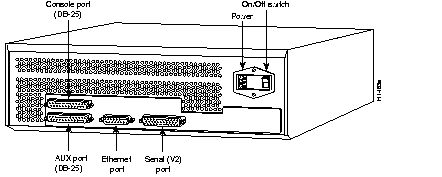
Figure A-5 shows the X.21 cable assembly, and Table A-9 and Table A-9 list the cable pinouts and signal descriptions.
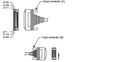
| 72-0683-02 Connections5 | ||||
|---|---|---|---|---|
| From | Signal | Type | To | Signal |
| J1-5 | MUX SEL | J1-38 | GND | |
| J1-36 | 449 GND | J2-8 | X.21 GND | |
| J1-41 J1-25 | 449 DTR | Jumper | J1-6 J1-22 | 449 CTS |
| J1-41 J1-25 | 449 DTR | Jumper | J1-8 J1-24 | 449 DSR |
| J1-43 J1-27 | 449 SCTE | Jumper | J1-37 J1-21 | 449 SCR |
| J1-1 J1-34 | 449 TXD | Twisted Pair | J2-2 J2-9 | X.21 TXD |
| J1-4 J1-20 | 449 RTS | Twisted Pair | J2-3 J2-10 | X.21 CTL |
| J1-35 J1-19 | 449 RXD | Twisted Pair | J2-4 J2-11 | X.21 RXD |
| J1-10 J1-26 | 449 RLSD | Twisted Pair | J2-5 J2-12 | X.21 IND |
| J1-2 J1-18 | 449 SCT | Twisted Pair | J2-6 J2-13 | X.21 CLK |
| 72-0737-01 Connections6 | ||||
|---|---|---|---|---|
| From | Signal | Type | To | Signal |
| J1-5 | MUX SEL | J1-38 | GND | |
| J1-36 | 449 GND | J2-8 | X.21 GND | |
| J1-41 J1-25 | 449 DSR | Jumper | J1-8 J1-24 | 449 DTR |
| J1-35 J1-19 | 449 TXD | Twisted Pair | J2-2 J2-9 | X.21 TXD |
| J1-6 J1-22 | 449-RTS | Twisted Pair | J2-3 J2-10 | X.21 CTL |
| J1-1 J1-34 | 449 RXD | Twisted Pair | J2-4 J2-11 | X.21 RXD |
| J1-10 J1-26 | 449 RLSD | Twisted Pair | J2-5 J2-12 | X.21 IND |
| J1-43 J1-27 | 449 SCT | Twisted Pair | J2-6 J2-13 | X.21 CLK |
| J1-17 | DCE SEL | J1-44 | ||
| J1-15 | Chassis GND | J2-1 | ||
Figure A-6 shows the EIA-530 serial cable assembly, and Table A-11 lists the pinouts and signal descriptions.
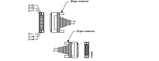
| 72-0732-01 Connections | ||||
|---|---|---|---|---|
| 50 Pin1 | Signal Name | Direction | 25 Pin | Type |
| J1-5 J1-38 | Looped | NC | Jumper | |
| J1-1 J1-34 | TXD + TXD - |   | J2-2 J2-14 | Twisted Pair |
| J1-35 J1-19 | RXD + RXD - |   | J2-3 J2-16 | Twisted Pair |
| J1-4 J1-20 | RTS + RTS - |   | J2-4 J2-19 | Twisted Pair |
| J1-6 J1-22 | CTS + CTS - |   | J2-5 J2-13 | Twisted Pair |
| J1-10 J1-26 | RLSD + (RR +) RLSD - (RR -) |   | J2-8 J2-10 | Twisted Pair |
| J1-2 J1-18 | SCT + SCT - |   | J2-15 J2-12 | Twisted Pair |
| J1-37 J1-21 | SCR + SCR - |   | J2-17 J2-9 | Twisted Pair |
| J1-43 J1-27 | SCTE + (TT +) SCTE - (TT -) |   | J2-24 J2-11 | Twisted Pair |
| J1-7 | LL |  | J2-18 | Twisted Pair |
| J1-48 J1-36 | Ground | J2-23 J2-7 | Twisted Pair | |
| J1-15 | Shield | J2-1 | Single Wire | |
| J1-8 J1-24 | DCE Ready Ground |  | J2-6 J2-23 | Twisted Pair |
| J1-41 | DTE Ready |  | J2-20 | Twisted Pair |
The following table provides theBRI port pinout.
Table A-12 BRI Port Pinout (RJ-45)
| 8 Pin7 | TE1 | NT2 | Polarity |
|---|---|---|---|
| 3 | Transmit | Receive | + |
| 4 | Receive | Transmit | + |
| 5 | Receive | Transmit | - |
| 6 | Transmit | Receive | - |
Figure A-7 shows the Ethernet (AUI) cable assembly, and Table A-12 lists the cable pinouts and signal descriptions.

| Pin8 | Ethernet Circuit | Signal Name |
|---|---|---|
| 3 | DO-A | Data Out Circuit A |
| 10 | DO-B | Data Out Circuit B |
| 11 | DO-S | Data Out Circuit Shield |
| 5 | DI-A | Data In Circuit A |
| 12 | DI-B | Data In Circuit B |
| 4 | DI-S | Data In Circuit Shield p |
| 7 | CO-A | Control Out Circuit A (not connected) |
| 15 | CO-B | Control Out Circuit B (not connected) |
| 8 | CO-S | Control Out Circuit Shield (not connected) |
| 2 | CI-A | Control In Circuit A |
| 9 | CI-B | Control In Circuit B |
| 1 | CI-S | Control In Circuit Shield |
| 6 | VC | Voltage Common |
| 13 | VP | Voltage Plus |
| 14 | VS | Voltage Shield (L25 and M25) |
| Shell | PG | Protective Ground |
The following tables provide the Token Ring port pinouts for models 3202 and 3204:
| 9-Pin | Signal |
|---|---|
| 1 | -RX |
| 2 | NC1 |
| 3 | NC |
| 4 | NC |
| 5 | -TX |
| 6 | +RX |
| 7 | NC |
| 8 | NC |
| 9 | +TX |
| 9-Pin | Signal |
|---|---|
| 1 | -RX |
| 2 | GND |
| 3 | NC1 |
| 4 | GND |
| 5 | -TX |
| 6 | +RX |
| 7 | GND |
| 8 | GND |
| 9 | +TX |
|
|