|
|

Table Of Contents
Troubleshooting Lightweight Access Points
Guidelines for Using 1130AG Series Lightweight Access Points
Checking the Lightweight Access Point LEDs
Low Power Condition for Lightweight Access Points
Configuring Power Using Controller CLI Commands
Manually Configuring Controller Information Using the Access Point CLI
Configuring Controller Information
Clearing Manually Entered Controller Information
Manually Resetting the Access Point to Defaults
Returning the Access Point to Autonomous Mode
Using a WLAN Controller to Return the Access Point to Autonomous Mode
Using the MODE Button to Return the Access Point to Autonomous Mode
Obtaining the Autonomous Access Point Image File
Connecting to the Access Point Console Port
Obtaining the TFTP Server Software
Troubleshooting Lightweight Access Points
This chapter provides troubleshooting procedures for basic problems with the 1130AG series lightweight access point (model: AIR-LAP1131AG or AIR-LAP1131G). For the most up-to-date, detailed troubleshooting information, refer to the Cisco Technical Support and Documentation website at the following URL:
http://www.cisco.com/en/US/products/hw/wireless/tsd_products_support_category_home.html
Sections in this chapter include:
•
Guidelines for Using 1130AG Series Lightweight Access Points
•
•
•
•
•
•
•
Guidelines for Using 1130AG Series Lightweight Access Points
Keep these guidelines in mind when you use a 1130AG series lightweight access point:
•
Note
•
•
•
•
Using DHCP Option 43
You can use DHCP Option 43 to provide a list of controller IP addresses to the access points, enabling the access point to find and join a controller. For additional informataion, refer to the "Configuring DHCP Option 43 for Lightweight Access Points" section on page G-1.
Checking the Lightweight Access Point LEDs
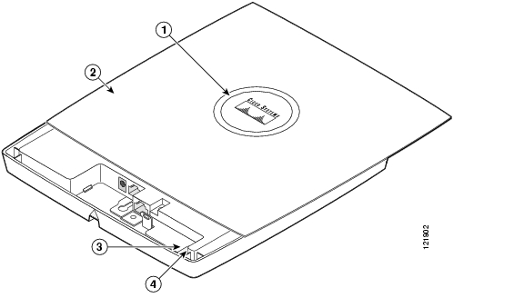
If your access point is not working properly, check the Status LED on the top panel or the Ethernet and Radio LEDs in the cable bay area. You can use the LED indications to quickly assess the unit's status. Figure 4-1 shows the access point LEDs.
Figure 4-1 Access Point LEDs
Note
Note
Note
The LED signals are listed in Table 4-1.
Table 4-1 LED Signals
Status LED
Boot loader status
Green
Green
Green
DRAM memory test ok.
Off
Blinking green
Blue-green
Initialize Flash file system.
Off
Green
Pink
Flash memory test ok.
Green
Off
Dark blue
Ethernet test ok.
Green
Green
Green
Starting Cisco IOS.
Association status
—
—
Light green
Normal operating condition, but no wireless client devices are associated with the unit.
—
—
Blue
Normal operating condition, at least one wireless client device is associated with the unit.
Operating status
Green
—
—
Ethernet link is operational.
Blinking green
—
—
Transmitting or receiving Ethernet packets.
—
Blinking green
—
Transmitting or receiving radio packets.
—
—
Blinking
dark blueSoftware upgrade in progress
Slow blinking green
—
—
Hybrid-REAP standalone mode
Boot loader warnings
Off
Off
Yellow
Ethernet link not operational.
Red
Off
Yellow
Ethernet failure.
Amber
Off
Yellow
Configuration recovery in progress
(Mode button pressed for 2 to 3 seconds).Off
Red
Pink
Image recovery
(Mode button pressed for 20 to 30 seconds)Blinking green
Red
Blinking pink and off
Image recovery in progress and Mode button is released.
Boot loader errors
Red
Red
Red
DRAM memory test failure.
Off
Red
Blinking red and blue
Flash file system failure.
Off
Amber
Blinking red and blue-green
Environment variable (ENVAR) failure.
Amber
Off
Blinking red and yellow
Bad MAC address.
Red
Off
Blinking red and off
Ethernet failure during image recovery.
Amber
Amber
Blinking red and off
Boot environment error.
Red
Amber
Blinking red and off
No Cisco IOS image file.
Amber
Amber
Blinking red and off
Boot failure.
Cisco IOS errors
Blinking amber
—
—
Transmit or receive Ethernet errors.
—
Blinking amber
—
Maximum retries or buffer full occurred on the radio.
Red
Red
Amber
Software failure; try disconnecting and reconnecting unit power.
—
—
Amber
General warning, insufficient inline power (see the "Low Power Condition for Lightweight Access Points" section).
Controller status
—
—
Alternating green, red , and amber1
Connecting to the controller.
Note
—
—
Blinking dark blue
Loading the access point image file.
1 This status indication has the highest priority and overrides other status indications.
Low Power Condition for Lightweight Access Points
Warning
The lightweight access point can be powered from the 48-VDC power module or from an in-line power source. The access point supports the IEEE 802.3af power standard, Cisco Pre-Standard PoE protocol, and Cisco Intelligent Power Management for in-line power sources.
For full operation, the access point requires 12.95 W of power. The power module and Cisco Aironet power injectors are capable of supplying the required power for full operation, but some inline power sources are not capable of supplying 12.95 W. Also, some high-power inline power sources, might not be able to provide 12.95 W of power to all ports at the same time.
Note
Note
On power up, the access point is placed into low power mode (both radios are disabled), Cisco IOS software loads and runs, and power negotiation determines if sufficient power is available. If there is sufficient power then both radios are turned on; otherwise, the access point remains in low power mode with one or both radios disabled to prevent a possible over-current condition. In low power mode, the access point activates the Status LED low power error indication (see the "Checking the Lightweight Access Point LEDs" section).
Intelligent Power Management
The access point requires 12.95 W of power for full power operation with both radios, but only needs 6.3 W of power when operating in low power mode with both radios disabled. To help avoid an over-current condition with low power sources and to optimize power usage on Cisco switches, Cisco developed Intelligent Power Management, which uses Cisco Discovery Protocol (CDP) to allow powered devices (such as your access point) to negotiate with a Cisco switch for sufficient power.
The access point supports Intelligent Power Management and as a result of the power negotiations, the access point will either enter full power mode or remain in low power mode with one or both radios disabled.
Note
Some Cisco switches that are capable of supplying sufficient power require a software upgrade to support Intelligent Power Management. If the software upgrade is not desired, you can configure the access point to operate in pre-standard compatibility mode and the access point automatically enters full power mode if these Cisco switches are detected in the received CDP ID field.
When the access point determines that sufficient power is not available for full-power operation, one or both readios are deactivated and the Status LED turns amber to indicate low power mode (see Table 4-1).
If your Cisco switch is capable of supplying sufficient power for full operation but the access point remains in low-power mode, your access point or your switch (or both) might be misconfigured (see Table 4-2.
If your inline power source is not able to supply sufficient power for full operation, you should consider these options (see Table 4-2):
•
•
•
Configuring Power Using Controller CLI Commands
Intelligent Power Management support is dependent on the version of software resident in the Cisco switch that is providing power to the access point. Each Cisco switch should be upgraded to support Intelligent Power Management. Until the software is upgraded, you can use your controller to configure the access point to operate with older switch software using these controller CLI commands:
1) config ap power pre-standard enable <ap>where <ap> is the access point name on the controller2) config ap power injector enable <ap> <switch port MAC address>(where <ap> is the access point name on the controllerand <switch port MAC address> is the MAC address of the switch port to which the access point is connected)
Note
You can use these controller CLI commands to inform the access point of the following:
•
•
Caution
Refer to Table 4-2 for information on when to use these special CLI controller commands and the corresponding Cisco switch power command.
Table 4-2 Using CLI Power Commands
AC power module
None required
power inline never
Cisco switch that supports Intelligent Power Management1
None required
power inline auto
Cisco switch that does not support Intelligent Power Management1
config ap power pre-standard enable
power inline auto
Power injector2 used with a Cisco switch that supports Intelligent Power Management1
None required
power inline never3
Power injector2 used with a Cisco switch that does not support Intelligent Power Management1
config ap power injector enable
power inline never
Power injector used with a non-Cisco switch
None required
-
802.3af compliant non-Cisco switches
None required
-
1 You should check the release notes for your Cisco power source to determine which Cisco IOS release supports Intelligent Power Management. Support for Intelligent Power Management might not be currently available for your Cisco power source.
2 Power injector must be AIR-PWRINJ3 or AIR-PWRINJ-FIB.
3 Cisco switches that support Intelligent Power Management always configure the use of a power injector at the switch.
Manually Configuring Controller Information Using the Access Point CLI
In a new installation, when your access point is unable to reach a DHCP server, you can manually configure needed controller information using the access point CLI. For information on how to connect to the console port, see the "Connecting to the Access Point Console Port" section.
Note
The static information configured with the CLI commands are used by the access point to connect with a controller. After connecting with the controller, the controller reconfigures the access point with new controller settings, but the static IP addresses for the access point and the default gateway are not changed.
Configuring Controller Information
To manually configure controller information on a new (out-of -the-box) access point using the access point CLI interface, you can use these EXEC mode CLI commands:
AP# lwapp ap ip address <IP address> <subnet mask>AP# lwapp ip default-gateway IP-addressAP# lwapp controller ip address IP-addressAP# lwapp ap hostname nameWhere name is the access point name on the controller.
Note
Clearing Manually Entered Controller Information
When you move your access point to a different location in your network, you must clear the manually entered controller information to allow your access point to associate with a different controller.
Note
To clear or remove the manually entered controller information, you can use these EXEC mode CLI commands:
clear lwapp ap ip addressclear lwapp ip default-gatewayclear lwapp controller ip addressclear lwapp ap hostnameManually Resetting the Access Point to Defaults
You can manually reset your access point to default settings using this EXEC mode CLI command:
Note
clear lwapp private-configReturning the Access Point to Autonomous Mode
You can return a lightweight access point to autonomous mode by loading a Cisco IOS release that supports autonomous mode (such as Cisco IOS Release 12.3(7)JA or earlier). If the access point is associated to a controller, you can use the controller to load the Cisco IOS release. If the access point is not associated to a controller, you can load the Cisco IOS release using TFTP.
Using a WLAN Controller to Return the Access Point to Autonomous Mode
Follow these steps to revert from lightweight mode to autonomous mode using a controller:
Step 1
config ap tftp-downgrade tftp-server-ip-address filename access-point-name(where:a) tftp-server-ip-address is the IP address of the TFTP serverb) filename is the full path and filname of the access point image file, such as D:/Images/c1130-k9w7-tar.123-7.JA.tarc) access-point-name is the name that identifies the access point on the ocntroller.)Step 2
Step 3
Using the MODE Button to Return the Access Point to Autonomous Mode
Follow these steps to return a lightweight access point to autonomous mode using the access point MODE button and a TFTP server:
Note
Step 1
Step 2
Step 3
Step 4
Step 5
Step 6
Step 7
Step 8
Step 9
MODE Button Setting
The lightweight access point MODE button is configured from your Cisco Wireless LAN Controller. Use these controller CLI commands to view and configure the MODE button:
1) config ap rst-button enable <access-point-name>/all2) config ap rst-button disable <access-point-name>/all3) show ap config general <access-point-name>(Where access-point-name is the name that identifies the access point on the ocntroller.)Obtaining the Autonomous Access Point Image File
The autonomous access point image file can be obtained from the Cisco.com software center using these steps:
Note
Step 1
http://tools.cisco.com/support/downloads/pub/MDFTree.x?butype=wireless
Step 2
Step 3
Step 4
Step 5
Step 6
Step 7
Step 8
Step 9
Step 10
Step 11
Step 12
Step 13
Step 14
Step 15
Step 16
Step 17
Connecting to the Access Point Console Port
The console port is enabled during power up for diagnostic and monitoring purposes, which might be helpful if the access point is unable to associate to a controller. You can connect a PC to the console port using a DB-9 to RJ-45 serial cable.
Caution
Note
Follow these steps to view the power up sequences by connecting to the access point console port:
Step 1
Step 2
Figure 4-2 Console Port Location
Step 3
When you have finished using the console port, you must remove the serial cable from the access point.
Obtaining the TFTP Server Software
You can download TFTP server software from several web sites. Cisco recommends the shareware TFTP utility available at this URL:
Follow the instructions on the website for installing and using the utility.
![]()
![]()
![]()
![]()
![]()
![]()
![]()
![]()
Posted: Thu Apr 26 01:50:18 PDT 2007
All contents are Copyright © 1992--2007 Cisco Systems, Inc. All rights reserved.
Important Notices and Privacy Statement.